
Seal plate, seal member that is used in seal plate, and method for manufacturing the same

a technology which is applied in the field of seal plate and seal member, can solve the problems of insufficient durability and higher cost in the present state of things, and achieve the effects of excellent radical resistance, excellent corrosion resistance and extended life of the seal member

Active Publication Date: 2014-11-18
VALQUA LTD
View PDF27 Cites 11 Cited by
  • Summary
  • Abstract
  • Description
  • Claims
  • Application Information

AI Technical Summary

Benefits of technology

[0063]In accordance with the present invention, the seal member is provide with the vacuum seal part and the radical seal part, and the rubber elastic body that configures the vacuum seal part and the radical seal part is bonded to the outer edge part of the seal plate. Consequently, the present invention can provide a seal plate, a seal member that is used in a seal plate, and a method for manufacturing the seal plate and the seal member, in which the life of a seal member is extended by preventing the seal member that is used in a seal plate from being exposed to a treatment gas, and the seal member is prevented from dropping out of a groove of a seal plate and rolling in a groove.
[0064]Moreover, the radical seal part is configured by covering the rubber elastic body with the radical resistant body that is provided with an excellent corrosion resistance and an excellent radical resistance. Consequently, the present invention can provide a seal plate, a seal member that is used in a seal plate, and a method for manufacturing the seal plate and the seal member, in which the radical seal part is provided with an excellent protection function to a treatment gas such as a corrosive gas and an active gas and the life can be dramatically extended.

Problems solved by technology

However, the durability is not sufficient and a cost is higher in the present state of things.

Method used


Image

  • Seal plate, seal member that is used in seal plate, and method for manufacturing the same
  • Seal plate, seal member that is used in seal plate, and method for manufacturing the same
  • Seal plate, seal member that is used in seal plate, and method for manufacturing the same

Examples


Embodiment Construction

[0095]An embodiment (example) of the present invention will be described below in detail with reference to the drawings.

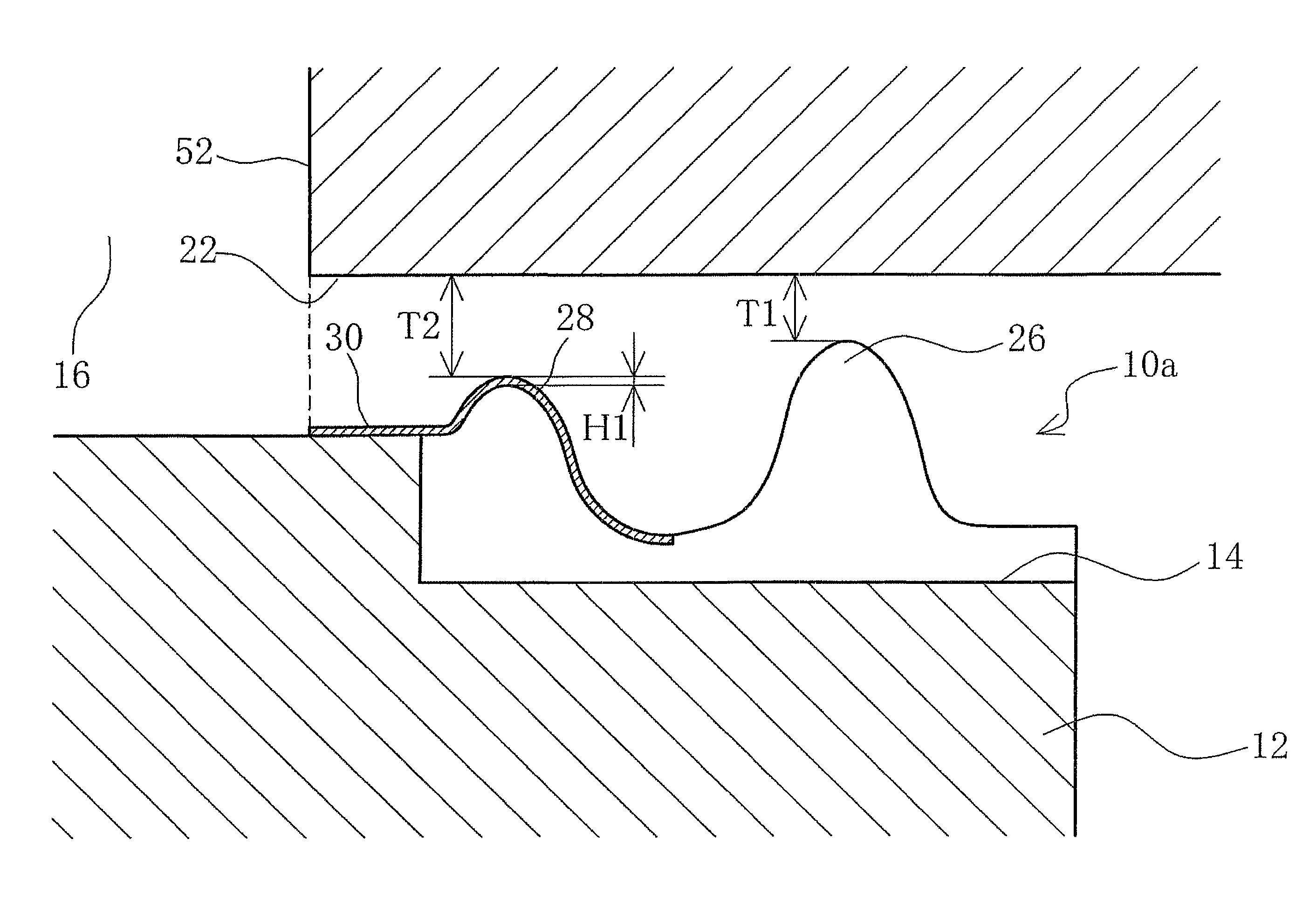
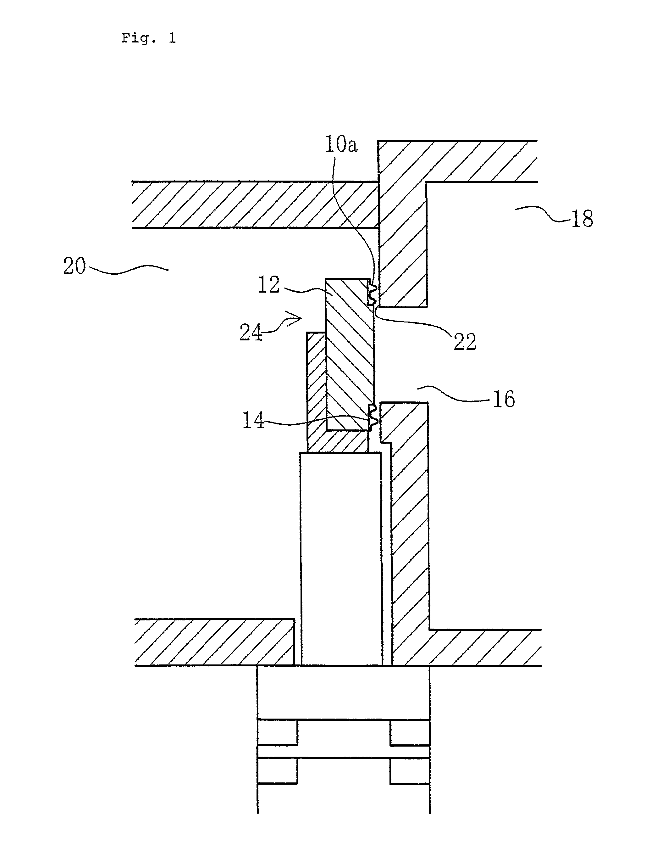
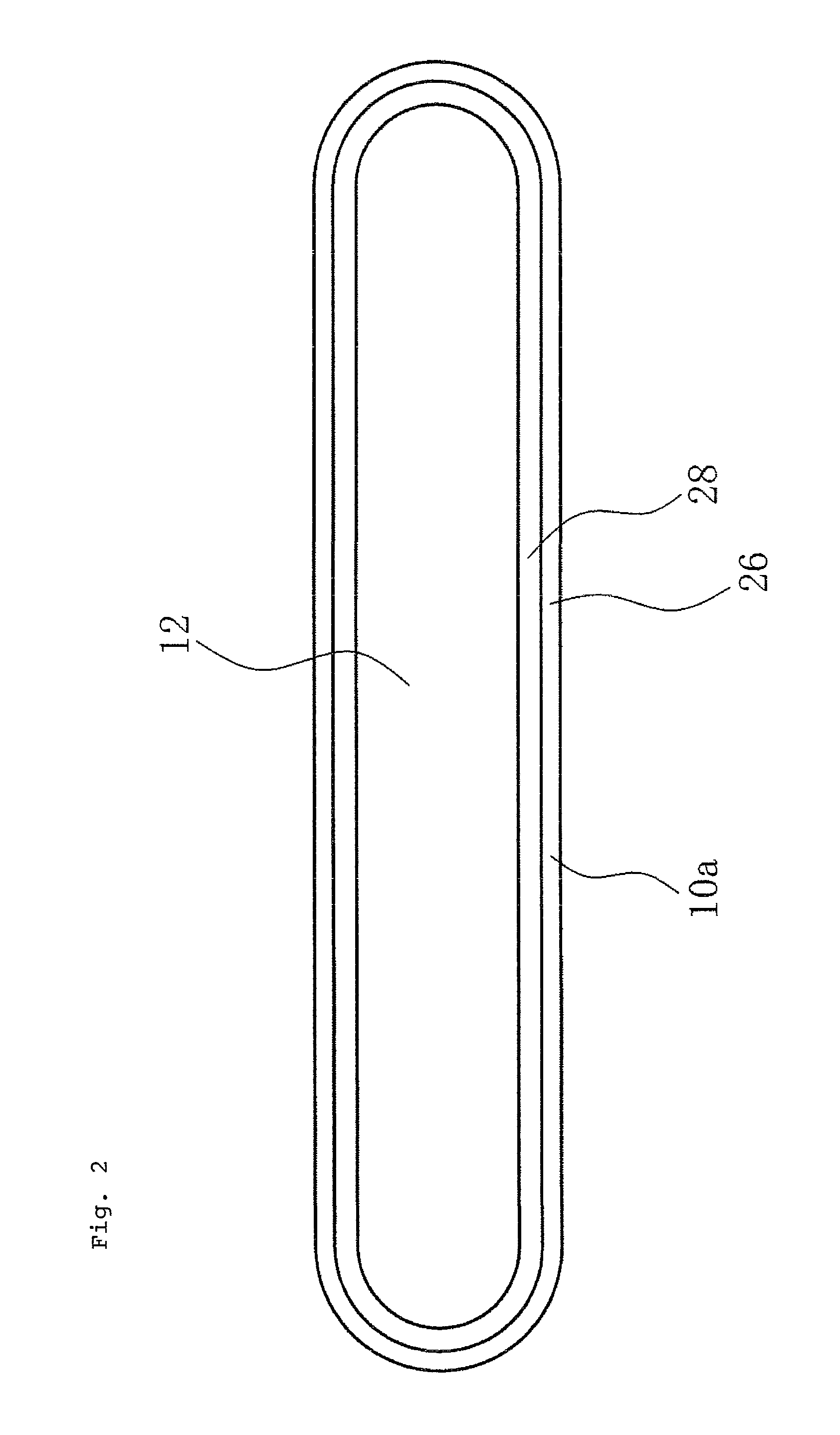
[0096]FIG. 1 is a schematic cross-sectional view showing a vacuum gate valve that is provided with a seal member in accordance with an embodiment of the present invention. FIG. 2 is a front elevation view showing a seal plate that is provided with a seal member in accordance with an embodiment of the present invention. FIG. 3 is a schematic cross-sectional view showing a seal plate that is provided with a seal member in accordance with a first embodiment of the present invention. FIGS. 4 to 8 are the schematic cross-sectional views showing a seal plate that is provided with a seal member in accordance with the second to sixth embodiments of the present invention.

[0097]A seal plate in accordance with the present invention and a seal member that is used for the seal plate are user for a vacuum gate valve that has been formed in a gate opening part that is a taking pa...


PUM


Abstract

In a vacuum gate valve, a seal member for sealing a gate opening part is bonded to an outer edge part of a planar seal plate that is disposed in such a manner that the planar seal plate is opposed to a valve seat surface of the gate opening part and comes into contact with the valve seat surface. The seal member includes a vacuum seal part that is located on a side farther from the gate opening part and maintains the sealability of the gate opening part when the gate opening part is closed, and also includes a radical seal part that is located on a side closer to the gate opening part and that prevents the seal member from being affected by a treatment gas in the gate opening part when the gate opening part is closed. The vacuum seal part is made of a rubber elastic body, and the radical seal part is configured by providing a radical resistant body that is provided with an excellent radical resistance on the rubber elastic body.

Description

TECHNICAL FIELD[0001]The present invention relates to a seal plate, a seal member that is used in the seal plate, and a method for manufacturing the seal plate and the seal member that are disposed in a vacuum gate valve that is used for a semiconductor manufacturing apparatus or the like.BACKGROUND ART[0002]For a conventional semiconductor manufacturing apparatus for producing a silicon wafer, a processing and a treatment of a work such as an ion plating and a plasma etching have been carried out in a clean environment of a high vacuum, and a vacuum gate valve has been used in a gate opening part that is a taking part in and out of such a work.[0003]For a semiconductor manufacturing apparatus that is shown in FIG. 11 for instance, a vacuum gate valve 104 is used to seal a gate opening part 110 that is configured for taking a wafer in and out between a process chamber 106 and a transfer chamber 108.[0004]A seal plate 102 that is used in the vacuum gate valve 104 is made of a metal s...

Claims


Application Information

Patent Timeline
Patent Type & Authority Patents(United States)
IPC IPC(8): F16K51/02F16K3/02F16J15/08F16J15/10
CPCF16K51/02F16J15/104F16J15/102F16K3/0227F16K3/0218Y10T156/1043F16J15/10F16K3/02
Inventor HAMADE, MASATOYOSHIDA, TSUTOMUYOSHIDA, NOBUHIROTSUJI, KAZUAKI
Owner VALQUA LTD
Learn More