Piston pump for liquefied gas

a technology of liquefied gas and pump, which is applied in the direction of pump, positive displacement liquid engine, machine/engine, etc., can solve the problems of reducing the volume of propane, reducing the service life of the seal, so as to achieve the effect of increasing the volum

Inactive Publication Date: 2014-01-23
DELAWARE CAPITAL FORMATION
View PDF4 Cites 10 Cited by
  • Summary
  • Abstract
  • Description
  • Claims
  • Application Information

AI Technical Summary

Benefits of technology

[0005]The invention relates to a fuel supply system for a vehicle which uses an externally-mounted positive displacement pump to supply the LPG from the storage tank to the engine. More particularly, the invention relates to a multi-piston LPG injunction pump which is formed as a positive displacement pump for pumping the fluid from the storage tank to the engine intake manifold. In the preferred embodiment, the pump is provided in a dual piston configuration. The dual-piston pump is operated using the vehicle's pneumatic air system, wherein the pressurized air of this system alternatingly drives the two pistons of the dual-piston pump. The pump uses a common housing, with two piston bores in which the pistons are driven in a reciprocating manner. Each piston moves through a pumping stroke and a return stroke wherein the pistons move in opposite directions during their respective strokes. More specifically, as one piston moves through a pumping stroke, the opposite piston moves through a return stroke. Th

Problems solved by technology

However, such a configuration is known to have disadvantages associated therewith.
This lubrication lengthens the lif

Method used


Image

  • Piston pump for liquefied gas
  • Piston pump for liquefied gas
  • Piston pump for liquefied gas

Examples


Embodiment Construction

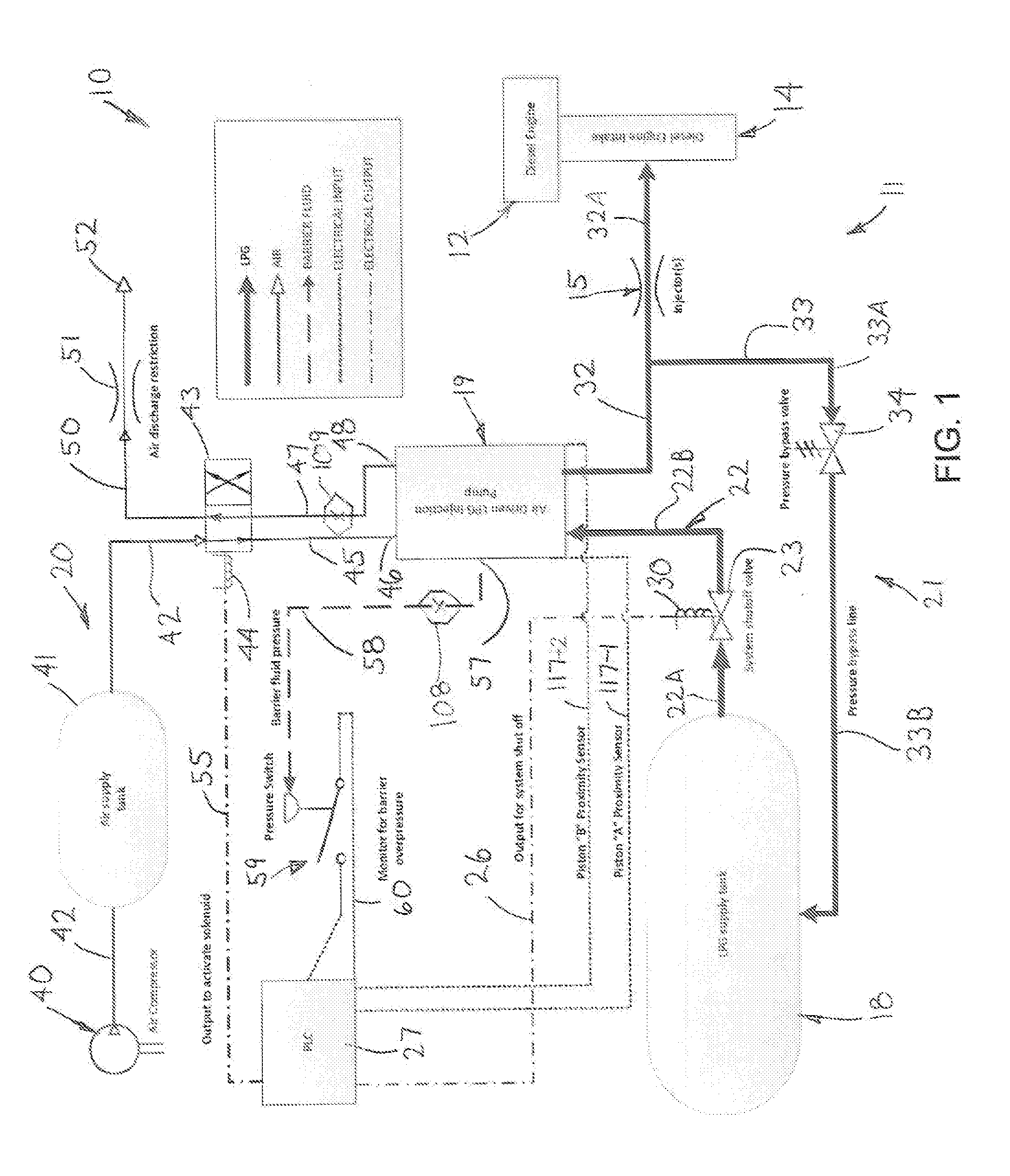
[0024]Referring to FIG. 1, the invention generally relates to a fuel supply system 10 for a vehicle which is generally designated by reference numeral 11 in FIG. 1. This vehicle 11 may be any conventional vehicle, but typically is a truck or the like in which a supplemental fuel, such as Liquefied Petroleum Gas (LPG or propane) or an LPG / Butane mix, is injected into the engine to improve performance thereof.

[0025]As to the vehicle 11, this vehicle 11 is powered by a conventional diesel engine 12, which includes a diesel engine intake 14 that may be constructed in the form of a fuel header or manifold. This engine intake 14 is supplied through one or more fuel injectors 15 wherein a representative one of such injectors 15 is illustrated in FIG. 1. For the diesel engine 12, it is known to inject the LPG into the fuel-air mixture to reduce emissions and increase engine performance. In known systems, the LPG may be pumped using an in-tank submersible turbine pump (not illustrated). The ...


PUM


Abstract

A fuel supply system for a vehicle uses a multi-piston LPG injunction pump which pumps fluid from a storage tank to an engine. The multi-piston pump uses the vehicle's pneumatic air system, wherein the pressurized air of this system alternatingly drives at least two pistons of the piston pump. Each piston moves through a pumping stroke and a return stroke wherein one piston moves through a pumping stroke, while the opposite piston moves through a return stroke. The pump includes barrier fluid chambers surrounding each of the pistons wherein during a pumping stroke of one piston, a first barrier fluid chamber associated with the one piston decreases in volume as the piston displaces through its pumping stroke. This reduction in volume of the barrier chamber drives the barrier fluid out of the first barrier fluid chamber into a second barrier fluid chamber associated with the second piston. By driving the barrier fluid into this second chamber, this pressurizes the second chamber and effects the displacing movement of the second piston through its return stroke as the barrier fluid chamber increases in volume through the movement of the second piston.

Description

CROSS REFERENCE TO RELATED APPLICATIONS[0001]This application asserts priority from provisional application 61 / 583,430, filed on Jan. 5, 2012 which is incorporated herein by reference.FIELD OF THE INVENTION[0002]The invention relates to a multi-piston pump and more particularly to a multi-piston liquid propane injection pump for a vehicle.BACKGROUND OF THE INVENTION[0003]In conventional diesel engines, it is known to inject liquid propane (LPG) into the fuel-air mixture in the fuel header or manifold of the engine. This is done to reduce emissions and increase performance of the vehicle. Typically, the vehicle would include an LPG tank and a pump which is in fluid communication with the LPG tank and pumps the LPG or other fluid into the engine manifold. In a known configuration, such a pump may be an in-tank, submersible turbine pump. However, such a configuration is known to have disadvantages associated therewith.[0004]It therefore is an object of the invention to overcome disadva...

Claims


Application Information

Patent Timeline
IPC IPC(8): F04B9/117
CPCF04B9/117F04B9/111F04B9/1176
Inventor FREY, MICHAEL E.FOSTER, RICHARD E.WALTERS, MICHAEL D.
Owner DELAWARE CAPITAL FORMATION
Why Eureka
Try Eureka