Apparatus for thermal spray coating

a technology of thermal spray and apparatus, which is applied in the direction of lighting and heating apparatus, combustion types, dental surgery, etc., can solve the problems of embrittlement of coating, complicated and expensive machine components, and consumption of resultant atomized droplets

Inactive Publication Date: 2005-04-21
XIOM CORPORATION
View PDF35 Cites 50 Cited by
  • Summary
  • Abstract
  • Description
  • Claims
  • Application Information

AI Technical Summary

Problems solved by technology

Attempts have been made to spray polymer materials in wire form using existing wire combustion technology; however, they have not succeeded as the air compression wave required to atomize the polymer wire is oriented so as to impinge the high temperature flame directly onto the feedstock material and thereby consuming the resultant atomized droplets.
The high temperature associated with this device can cause embrittlement of the coating.
This is a complicated and expensive component to machine.
The powder combustion process has been used to apply polymer materials; however, the flame temperature consumes 50 percent or more of the feedstock material.
Additionally, the relatively high temperature can burn the subsequent applied coating and/or cause embrittlement of the coating.
This is a complicated and expensive component to machine.
Combustion powder equipment does not provide for the generation of an aligned and oriented compression wave nor does it provide for cooling mixture air in the nozzle body whereby the flame temperature can be lowered.
The electric arc requires material in wire form which must be electrically conductive and therefore is not suitable as a means of spraying plastic materials.
The operating cost of the equipment further limit it as a device for economical on-site application of powder paint materials.
The detonation gun is large and requires a dedicated room.
It is used to apply hard dense coatings and is not suitable for polymer materials.
High velocity is unsuitable for applying polymer materials in that the pressures required for the fuel and oxidizing medium gases ensure a large flame and high temperature.
Also, the very high velocity is detrimental to the plastic droplets.
The temperature of the flame can degrade and embrittle the applied coating.
Further, the high operating cost of the equipment precludes it from ever becoming a viable means of applying low cost polymer

Method used


Image

  • Apparatus for thermal spray coating
  • Apparatus for thermal spray coating
  • Apparatus for thermal spray coating

Examples


Embodiment Construction

)

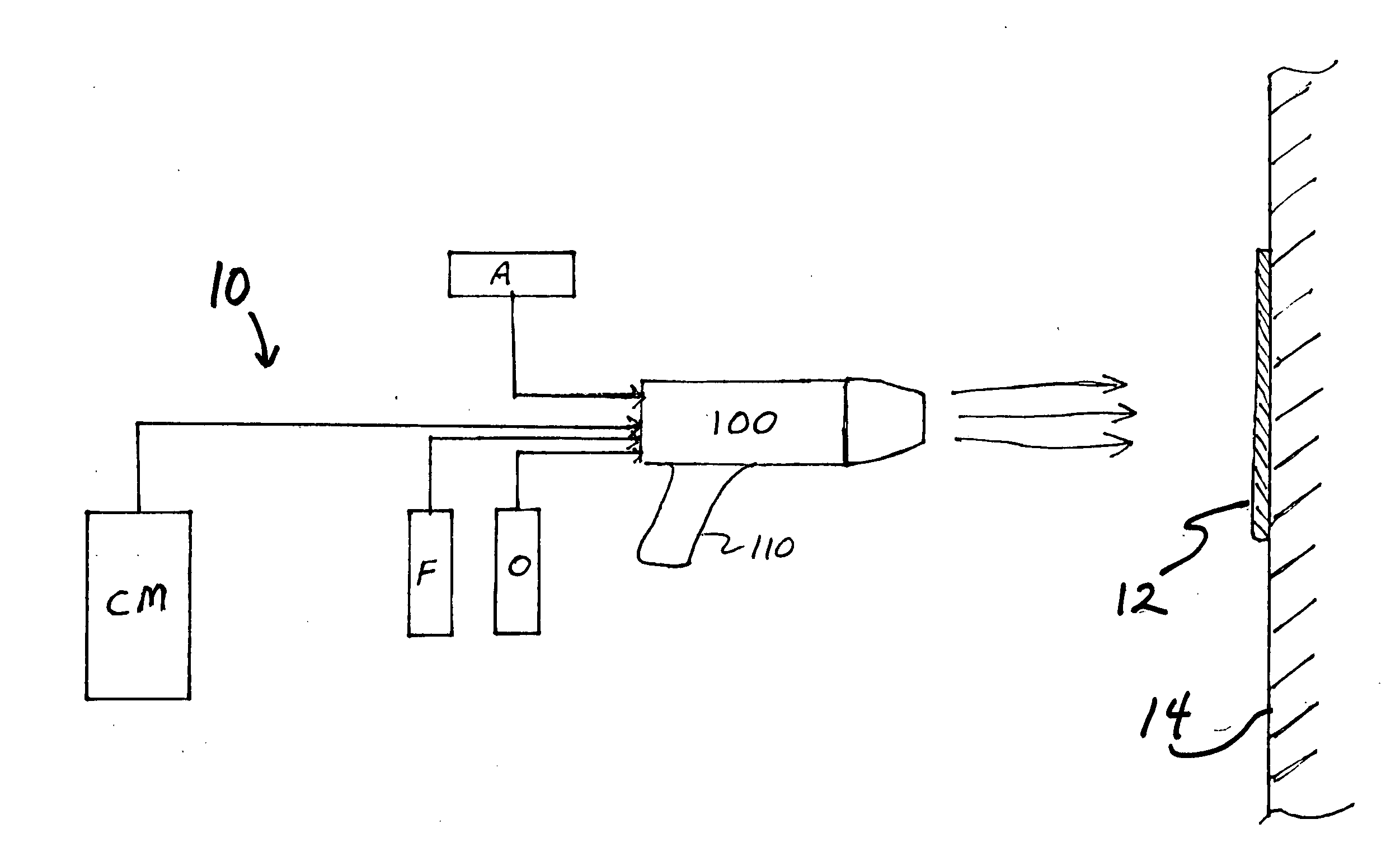
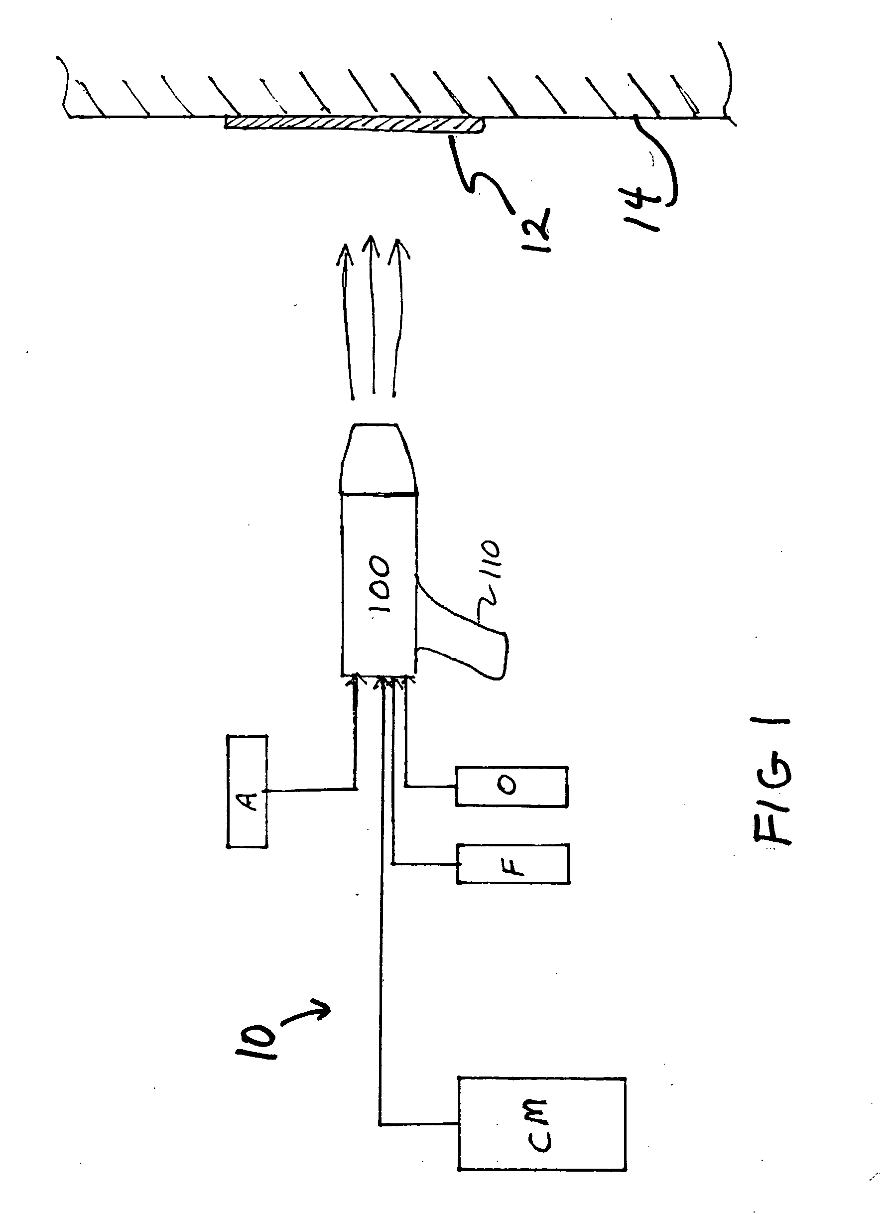
[0040] The present invention employs a vortex fuel-oxygen mixer and other innovations to provide a portable flame thermal spray gun with up to 100% efficiency in coating material deposition. It is simple and convenient to use at on-site locations and gives the user great flexibility in applying, for example, solid, smooth surface coatings, or porous, or rough surface coatings, for any particular polymer coating material of any desired thickness.

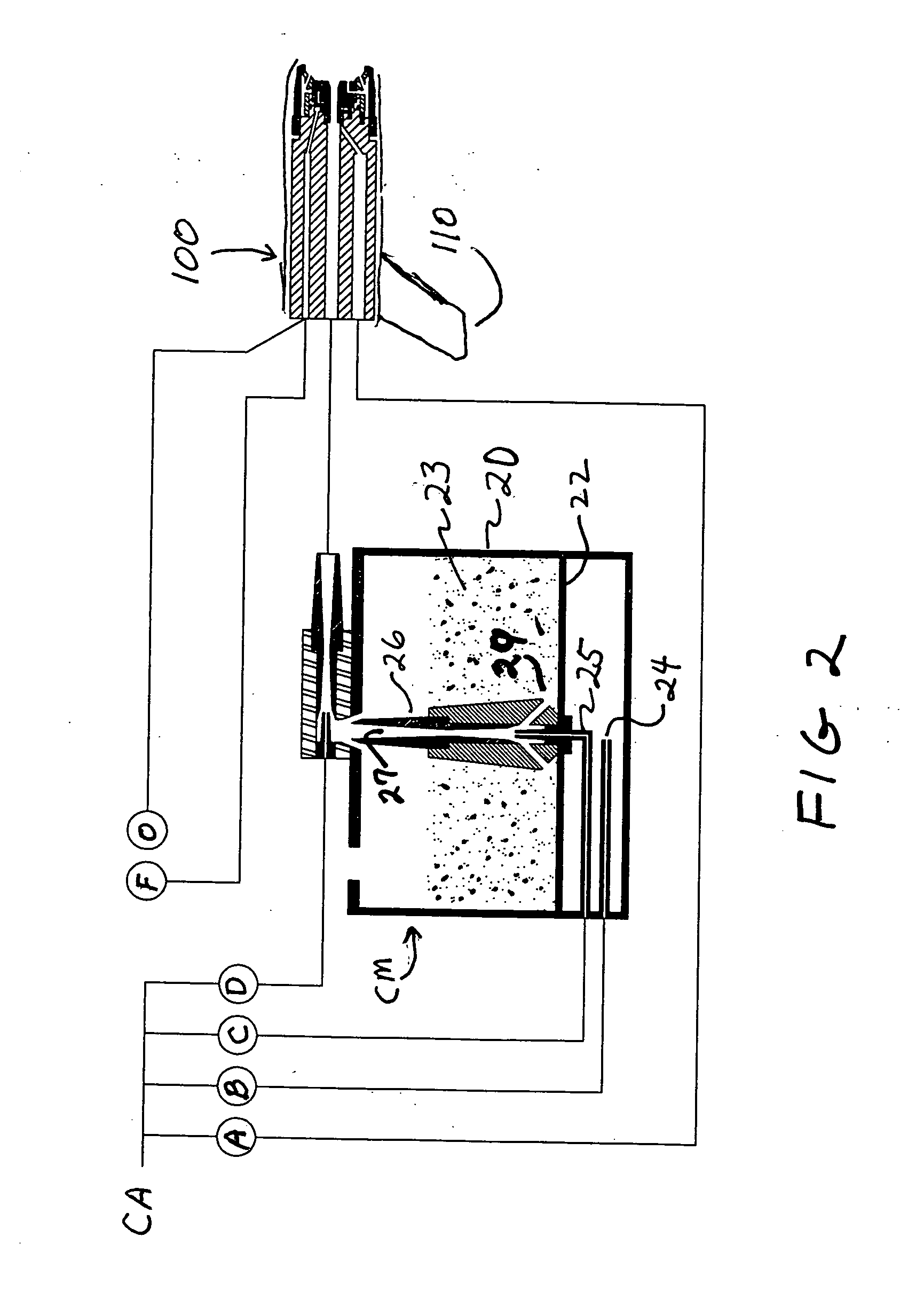
[0041] The thermally applied polymer and powder paint spray system consists of a spray gun with unique embodiments including a novel and unique powder feeder and regulated and controlled supply of air, oxygen, and propane. Polymer material to be applied is placed in the powder feeder whereby the material feed rate is controlled by a feed rate venturi and directed within the feeder to a material delivery venturi whereby the feedstock material to be applied is directed to the spray gun where it is melted and propelled to a substrate for appli...


PUM

PropertyMeasurementUnit
Sizeaaaaaaaaaa
Sizeaaaaaaaaaa
Particle sizeaaaaaaaaaa

Abstract

A system for thermal spray coating of a particulate material onto a substrate includes a spray gun apparatus having dual vortex chambers for the mixing of fuel gas and oxygen. The apparatus provides a jet flame resulting from a compression wave formed by compressed air. Dual venturis control the flow of fluidized coating material particles to provide smooth and controlled delivery of coating material to the spray gun.

Description

CROSS-REFERENCE TO RELATED APPLICATIONS [0001] This application claims priority to U.S. provisional application Ser. No. 60 / 509,948 filed Oct. 9, 2003, which is herein incorporated by reference.BACKGROUND [0002] 1. Field of the Invention [0003] The present invention is directed to apparatus for thermal spray coating, and particularly to a portable thermal spray coating gun for applying a polymer-containing coating material to a substrate. [0004] 2. Background of the Art [0005] The term “thermal spraying” refers to process in which a coating material feedstock is heated and propelled as individual droplets or particles onto the surface of a substrate. The coating material is heated by the applicator (e.g., a thermal spray gun) by using combustible gas or an electric arc and converted into molten or plastic droplets or particles, which are propelled out of the spray gun by compressed gas. When the coating material particles strike the substrate they flatten and form thin platelets (“s...

Claims


Application Information

Patent Timeline
IPC IPC(8): B05B7/14B05B7/20
CPCB05B7/205B05B7/1472B05B7/14B05B7/16B05B7/20
Inventor GARDEGA, THOMAS
Owner XIOM CORPORATION
Why Eureka
Try Eureka