Wear resistant layer for downhole well equipment

a technology of wear resistance and downhole well, applied in the direction of coating, fluid removal, cleaning apparatus, etc., can solve the problems of affecting the integrity of the wear mechanism, affecting the wear resistance of the wear resistance layer, so as to reduce the coefficient of friction and increase the wear resistance

Active Publication Date: 2009-02-10
INNOVEX DOWNHOLE SOLUTIONS INC
View PDF34 Cites 53 Cited by
  • Summary
  • Abstract
  • Description
  • Claims
  • Application Information

AI Technical Summary

Benefits of technology

[0012]The present disclosure provides a method, system, apparatus, and related alloy to provide a protective wear coating on a downhole component for a well. In at least one embodiment, the disclosure provides a synergistic use of a thermal spraying process in combination with a novel iron-based alloy. The thermal spraying process, such as twin wire arc spraying, melts the material to be deposited while a pressurized air stream sprays the molten material onto the downhole component. The coating operation takes place at low temperatures without fusion to the base material. Thus, there is no thermal deterioration of the base material, whose underlying properties remain unaffected. Coatings can be applied over small or large surfaces. The wear resistance is increased while providing a lower coefficient of friction by the wear resistant layer relative to a coefficient of friction of the downhole equipment without the wear resistant layer. In at least one embodiment, the disclosed process using the iron-based alloy can apply a much thicker coating than heretofore has been able to be applied without spalling and without necessitating an intermediate buffer layer.

Problems solved by technology

The most severe abrasive wear conditions occur when drilling through highly siliceous geological earth formations.
The consequence is an exposure of the pipe to wear mechanisms that may affect its integrity to a significant degree.
When drilling into mineral formations, the wear mechanism involved is mainly abrasion.
These wear situations are also encountered with other downhole equipments such as coiled tubing, downhole tools housing expensive instrumentation and other components exposed to longitudinal and rotational wear during well drilling operations.
However, this attempted solution resulted in a catastrophic failure that led to litigation, because the clamps allegedly either separated from the pipe downhole or caused drill pipe failure.
Another attempted solution was clamping rubber sleeves on the drill pipe, which also has not been successful.
Further, paints, epoxy coatings, and powder metallurgy resists oxidation, but are very unsuitable for the abrasion encountered in drilling through rock.
It is believed that this concept was not successful commercially, probably due to the fact that such processes are generally avoided as welding or fusion on the drill pipe with the intense heat.
Such processes may cause metallurgical changes in the base material and possible failure in the well bore that can cause the loss of millions of dollars in deeper wells.
Also, the alloys referenced in this patent are expensive cobalt-based alloys that require the use of intermediate, or so-called buffer layers, of high-alloyed austenitic steels.
Further, such processes would be fatal to downhole tools having instrumentation therein, where a downhole instrumentation tool can cost up to about half a million dollars.
Typically, the inside surfaces of drill pipe are coated with a corrosion resistant layer that may be damaged by the high temperatures generated during any external application by welding or fusion processes.
Thus, the '881 patent is similarly situated as the above '996 patent that requires higher temperatures and could cause metallurgical changes to the base material of the part and possible failure of the part downhole.
However, this article does not address known issues using this process of a peeling away of thicker layers from the base material, especially under wear conditions, for example, when the layers are 0.10 inches (2.5 millimeters) and greater.
Similarly, the article does not address known issues using this process of peeling away of thicker layers from the base material, especially under wear conditions.

Method used


Image

  • Wear resistant layer for downhole well equipment
  • Wear resistant layer for downhole well equipment
  • Wear resistant layer for downhole well equipment

Examples


Embodiment Construction

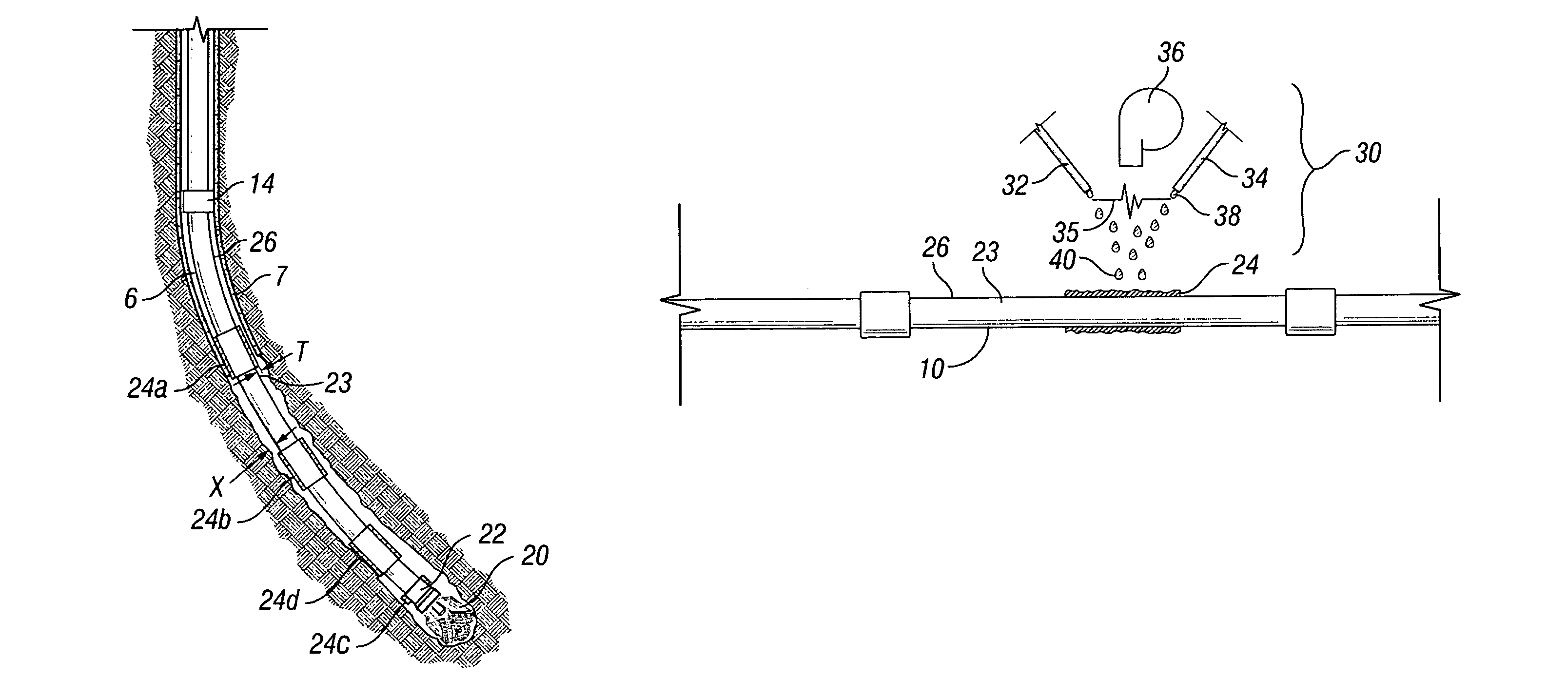
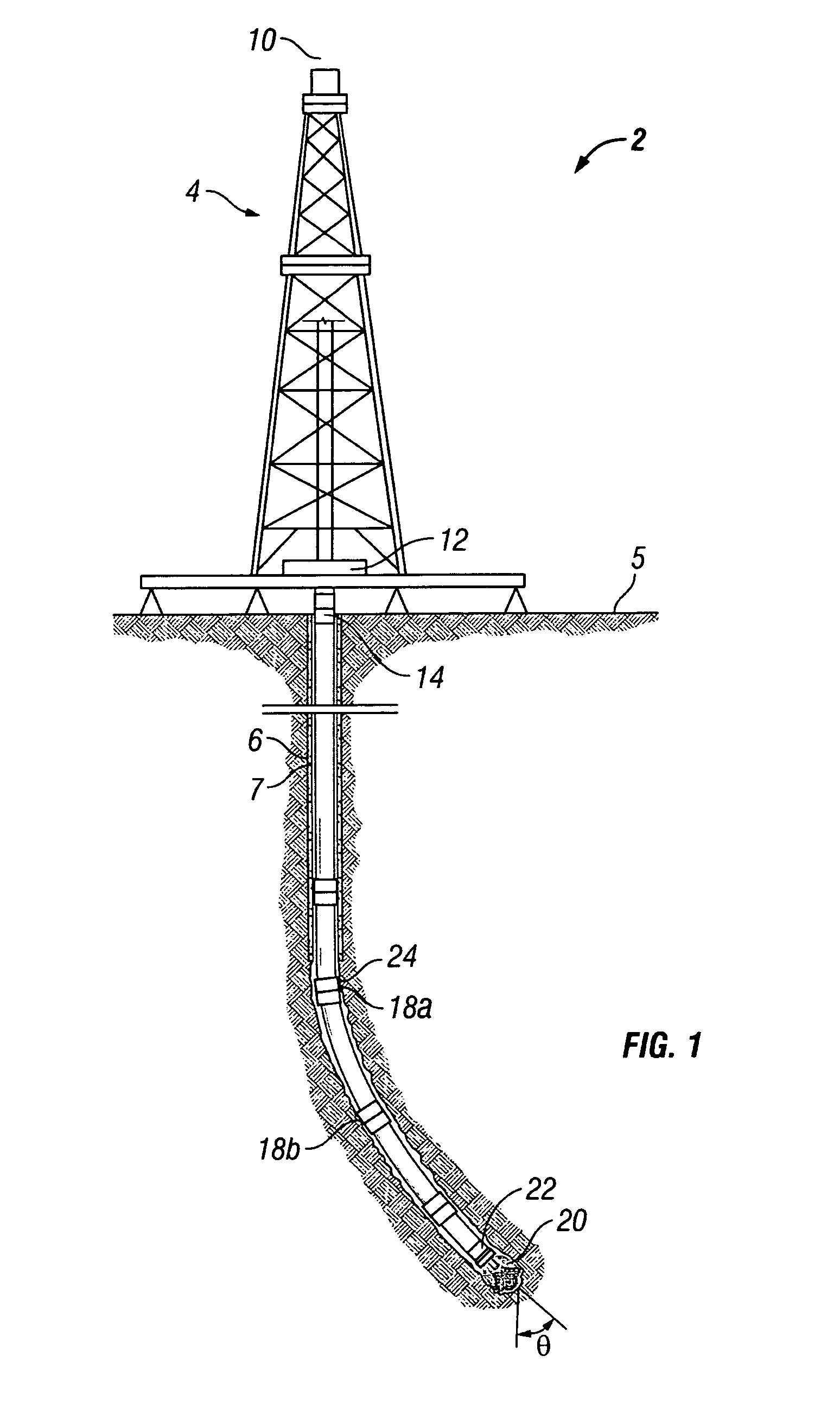
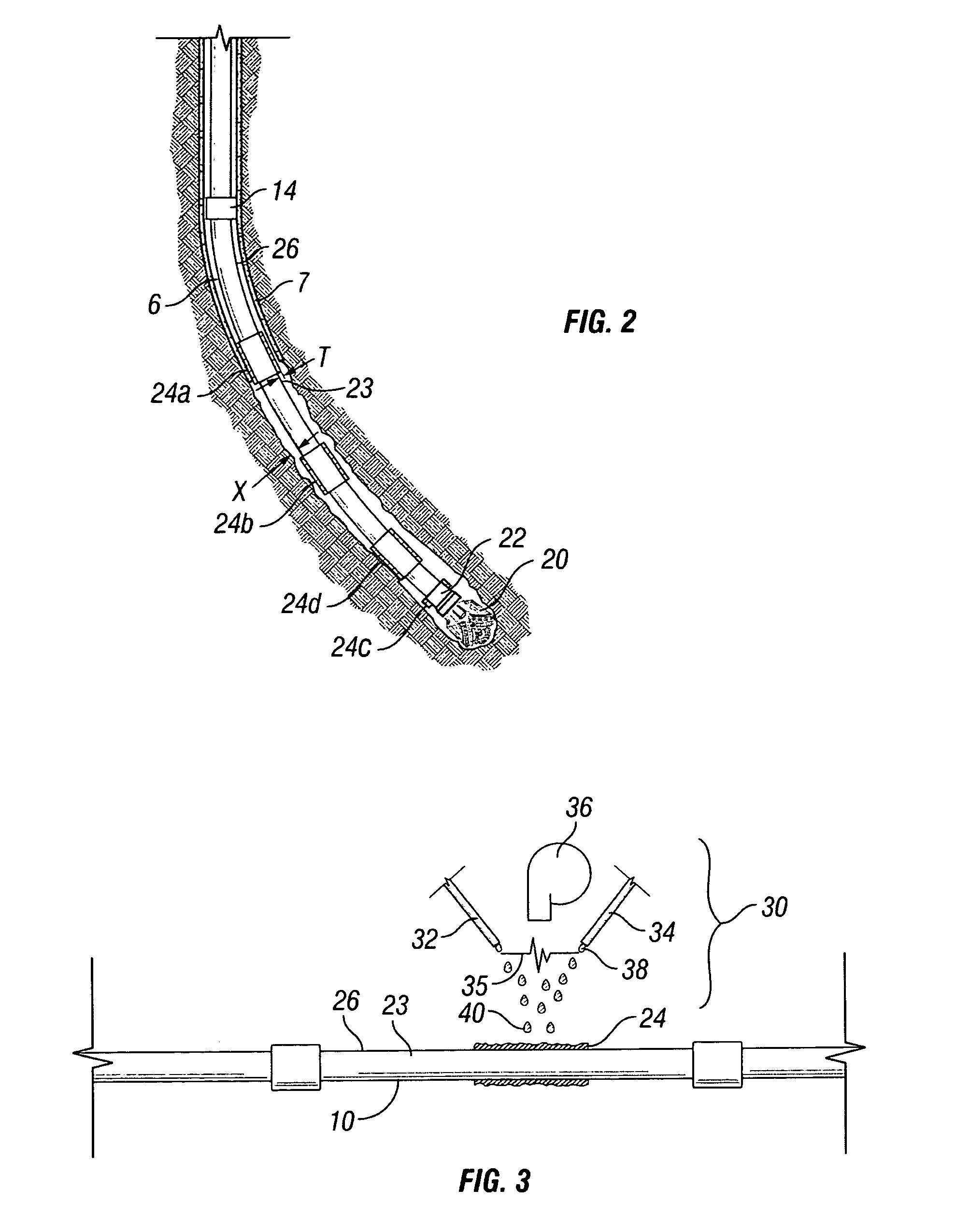
[0017]FIG. 1 is a cross-sectional schematic diagram of a drilling rig with an associated downhole assembly in a well bore. A well 2 is generally formed or serviced with a rig 4. The rig is stationed above the well location generally on a surface 5, such a ground surface, a seabed floor, or on a fixed or floating platform. The rig can be a drilling rig, a workover rig, or a service rig, or other rigs, depending on the operation desired. The well 2 includes a wellbore 6 that is generally lined with a casing 7. The casing 7 is generally a steel tubular member. A conduit 10 is used to form or service the well 2. The conduit can be a drilling pipe, coiled tubing, or other tubular goods of various sizes and cross sectional shapes. If the conduit 10 is jointed, a coupling 14 can be used to couple the joints of the conduit together. The term “coupled,”“coupling,” and like terms are used broadly herein and can include any method or device for securing, binding, bonding, fastening, attaching,...


PUM

PropertyMeasurementUnit
thickaaaaaaaaaa
thicknessaaaaaaaaaa
lengthaaaaaaaaaa

Abstract

The present disclosure provides a method, system, apparatus, and related alloy to provide a protective wear coating on a downhole component for a well through a synergistic use of a thermal spraying process in combination with a novel iron-based alloy. The thermal spraying process melts the material to be deposited while a pressurized air stream sprays the molten material onto the downhole component. The coating operation takes place at low temperatures without fusion or thermal deterioration to the base material. The wear resistance is increased while providing a lower coefficient of friction by the wear resistant layer relative to a coefficient of friction of the downhole equipment without the wear resistant layer. In at least one embodiment, the disclosed process using the iron-based alloy can apply a much thicker coating than heretofore has been able to be applied without spalling and without necessitating an intermediate buffer layer.

Description

[0001]This application claims the benefit of U.S. Provisional Application No. 60 / 627,387, filed Nov. 12, 2004 of the same title.FIELD OF THE INVENTION[0002]The invention relates to coatings applied to equipment. More specifically, the invention relates to protective wear resistant layers for downhole equipment in wells.BACKGROUND OF THE INVENTION[0003]Drilling wells for oil and gas recovery, as well as for other purposes, involves the use of drill pipes which, at one end, are equipped with a drilling bit whose function is to cut through various types of rock formations. The most severe abrasive wear conditions occur when drilling through highly siliceous geological earth formations. A rotational movement of the pipe ensures the progression of drilling. Pipes such as commonly used today come in sections of about 30 feet in length. These sections are connected to one another by means of tool joints. Typically these tool joints, which themselves are protected against wear by abrasion r...

Claims


Application Information

Patent Timeline
Patent Type & Authority Patents(United States)
IPC IPC(8): E21B17/10E21B41/02
CPCB32B15/011C22C38/02C22C38/04C22C38/32Y10S166/902C22C9/02C23C4/04C23C26/02C23C30/00C22C38/34C22C38/36C22C38/38C22C38/54C22C38/56C22C38/58C23C4/06E21B10/08E21B17/10
Inventor GAMMAGE, JOHN HUDSONDAEMEN, ROGER A.SCOTT, JOE LYNN
Owner INNOVEX DOWNHOLE SOLUTIONS INC
Why Eureka
Try Eureka