
Message holding device for removably suspending one or more articles therefrom

a technology of a message holding device and a message, which is applied in the field of message holding device, can solve the problems of requiring the use of both hands of the operator, limited items, and inability to permit prior art arrangements, and achieve the effect of raising funds

Inactive Publication Date: 2007-02-01
J R BIVENS & ASSOC
View PDF0 Cites 0 Cited by
  • Summary
  • Abstract
  • Description
  • Claims
  • Application Information

AI Technical Summary

Benefits of technology

[0017] Still another modification of the invention includes a product for use in a method of doing business to raise funds for an institution. The method includes the steps of creating a holding device for suspending articles therefrom, placing a message or picture relating to the institution on the device, and distributing the holding device in exchange for funds for supporting the institution's stated purpose to enable that institution to advertise as well as to provide a device as a useful message holder. The product is in the form of the holding device which includes first and second interconnected support plates having peripheral edges, the support plates being spaced from each other with each support plate having an inner surface facing the opposite support plate. A plurality of open pockets are disposed in the first plate inner surface and are open to the second plate inner surface. Each pocket includes a sloped bottom surface having a longitudinal axis declining away from an exterior peripheral edge the first plate to terminate in a recessed seat at the inward bottom thereof. Each pocket has its longitudinal axis aligned to define a different angular orientation from the remaining pockets relative to the peripheral edge. A ball is disposed within each pocket for movement along the bottom surface of the pocket, the balls being sized so that they are retained within their respective pockets between the plates wherein the spacing between plates enables an article to be passed between a ball and the second plate inner surface such that it is capable of being removably wedged therebetween by gravity forces. A mechanism is then provided for mounting the first plate to a generally vertically-oriented surface to permit a plurality of articles to be suspended simultaneously at a plurality of angular orientations relative to the device. Finally, an outer message holder element is rotatably mounted to the outer surface of the second plate to provide selective angular orientations thereof relative to the first and second plates, the outer message holder carrying a message or picture representing an institution for which funds are being raised and permitting the selective attachment of articles thereto at variable angular orientations.

Problems solved by technology

These types of devices have the disadvantage of requiring the use of both of an operator's hands for inserting and removing the article to be suspended therefrom.
Unfortunately, a major drawback to such devices is that the channel carrying the ball must be aligned substantially vertical in order to permit gravity to act on the ball and wedge the item between the ball and a surface.
Moreover, as a result of this arrangement, such items have been limited to the attachment of only one article from substantially one angular orientation.
While it would be very desirable to be able to a patch a plurality of items or articles to such a holding device, prior art arrangements have not permitted this.

Method used


Image

  • Message holding device for removably suspending one or more articles therefrom
  • Message holding device for removably suspending one or more articles therefrom
  • Message holding device for removably suspending one or more articles therefrom

Examples


Embodiment Construction

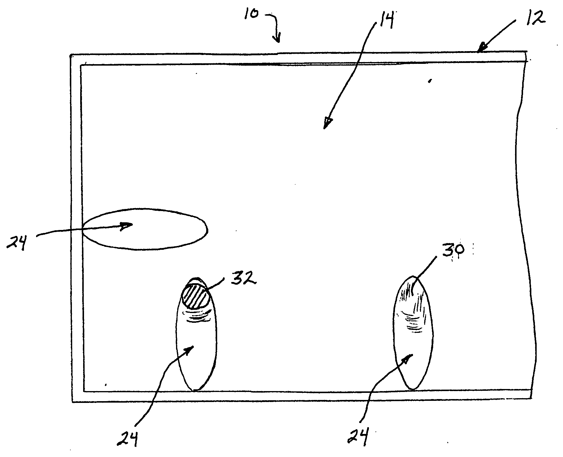
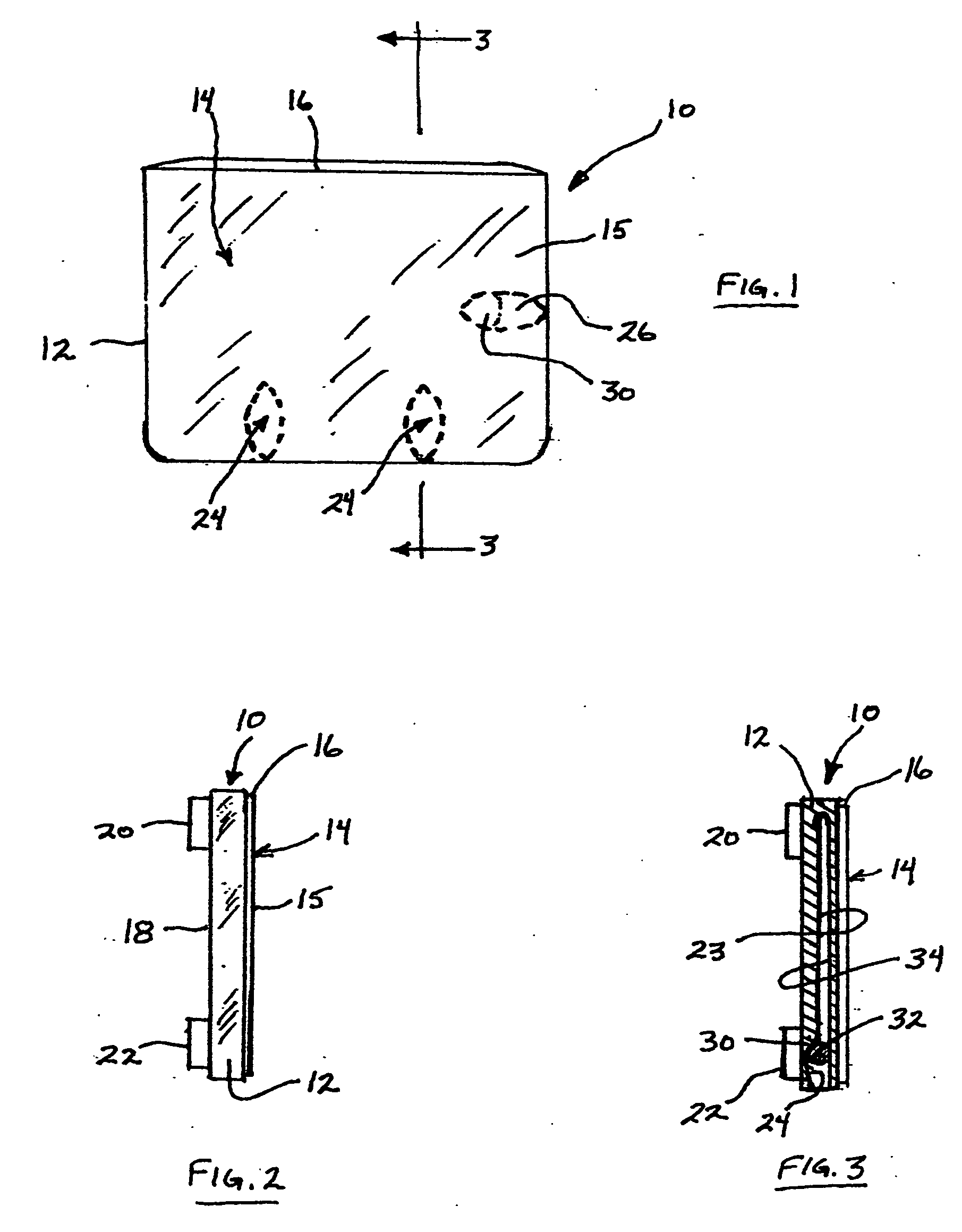
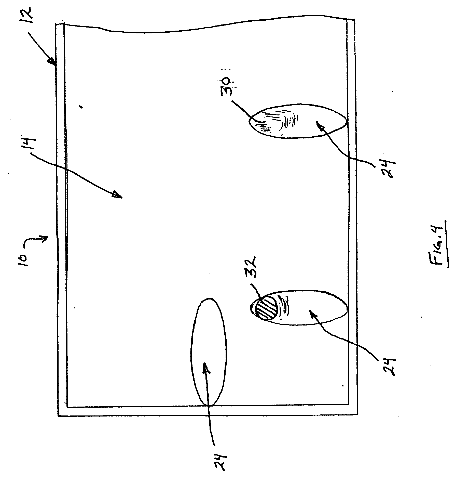
[0034] Referring first to FIGS. 1-4, the present invention is a message holding device 10 that includes a base member 12 and a cover member 14. The front surface of the cover member 14 may either be in the form of or include a sleeve 15 that can be opaque so that pictures and the like can be inserted through the opening 16 therein. Alternatively, the sleeve 15 can itself carry a message or be in the form of a picture as desired for advertising purposes and the like. The device 10 may be square, round or any other shape as desired. The rear portion or surface 18 of the base member 12 includes an attachment mechanism 20 of any desired type. This mechanism may be in the form of magnets 22, sticky tape elements or any other mounting mechanism known in the art such as hook and loop fasteners, and the like.

[0035] The inner surface 23 of the base member or element 12 of the device 10 includes a plurality of attachment members 24. In preferred form, there are three such attachment members ...


PUM


Abstract

A message holding device is disclosed and includes a first member having an inner surface, an outer surface and an exterior peripheral edge. A plurality of pockets are disposed in the first member inner surface. Each pocket is defined by an interior peripheral surface and a sloped bottom surface declining away from the first member exterior peripheral edge to form a seat at the bottom thereof. The pockets are aligned to define a plurality of angular orientations therebetween. A plurality of annular elements are provided, each being sized and shaped for disposition within and movement along one of the pockets. A second member is further provided and it has an inner surface, an outer surface and an exterior peripheral edge. The second member inner surface is secured to and spaced from the first member inner surface a distance such that each annular element is retained within its respective pocket and enables an article to be passed between the annular element and the second member inner surface such that it becomes wedged therebetween by gravity forces. Finally, a mechanism is provided for mounting the first member outer surface to a generally vertically-oriented surface to permit a plurality of articles to be mounted simultaneously at a plurality of angular orientations relative to the device.

Description

BACKGROUND OF THE INVENTION [0001] 1. Field of the Invention [0002] The present invention relates generally to a holder device for attaching items thereto and, more particularly, to such a device that is designed to attach to a vertical surface and utilizes a roller ball for suspending items therefrom. Specifically, the present invention relates to such a holder device is designed to provide a message center capable of attaching notes or the like thereto. [0003] 2. Description of the Prior Art [0004] There are many different types of devices for selectively holding paper and other items therefrom. Many such devices utilize spring clips or magnetic means to hold such items. These types of devices have the disadvantage of requiring the use of both of an operator's hands for inserting and removing the article to be suspended therefrom. To overcome this shortcoming, there have been many different types of holder devices designed which employ a ball which rides along and inclined surface...

Claims


Application Information

Patent Timeline
Patent Type & Authority Applications(United States)
IPC IPC(8): B42F17/00
CPCG09F1/12
Inventor BIVENS, GERALD R.
Owner J R BIVENS & ASSOC
Learn More