
Surgical device

a surgical device and stapling technology, applied in the field of surgical devices, can solve the problems of device difficulty, device difficulty, and device not being positioned satisfactorily within the patient's body, and achieve the effect of improving the patient's comfort and comfor

Active Publication Date: 2007-02-01
TYCO HEALTHCARE GRP LP
View PDF9 Cites 1030 Cited by
  • Summary
  • Abstract
  • Description
  • Claims
  • Application Information

AI Technical Summary

Benefits of technology

[0011] The surgical device may also includes a surgical member, e.g., a cutting and / or stapling element, disposed within the first jaw, and a second driver configured to cause relative movement of the surgical member in a direction parallel to the plane. The second driver may be configured to engage a second drive shaft rotatable about a rotation axis arranged in either a parallel or non-parallel, e.g., perpendicular, correspondence to the plane. An electromechanical driver may be employed to rotate the first rotatable drive shaft, such that the first rotatable drive shaft is rotated in a first direction to effect extending of the jaws and rotated in a second direction opposite to the first direction to effect closing of the jaws. In one embodiment, the first driver includes at least a spur gears, a worm and a worm gear in turning and gearing relationship with each other, and an externally-threaded screw fixedly connected at one end to the worm gear and in engagement with an internally-threaded bore of the second jaw, the rotation of the gears thereby causing relative movement of the first jaw and the second jaw.

Problems solved by technology

One problem with the foregoing surgical devices is that the devices may be difficult to maneuver.
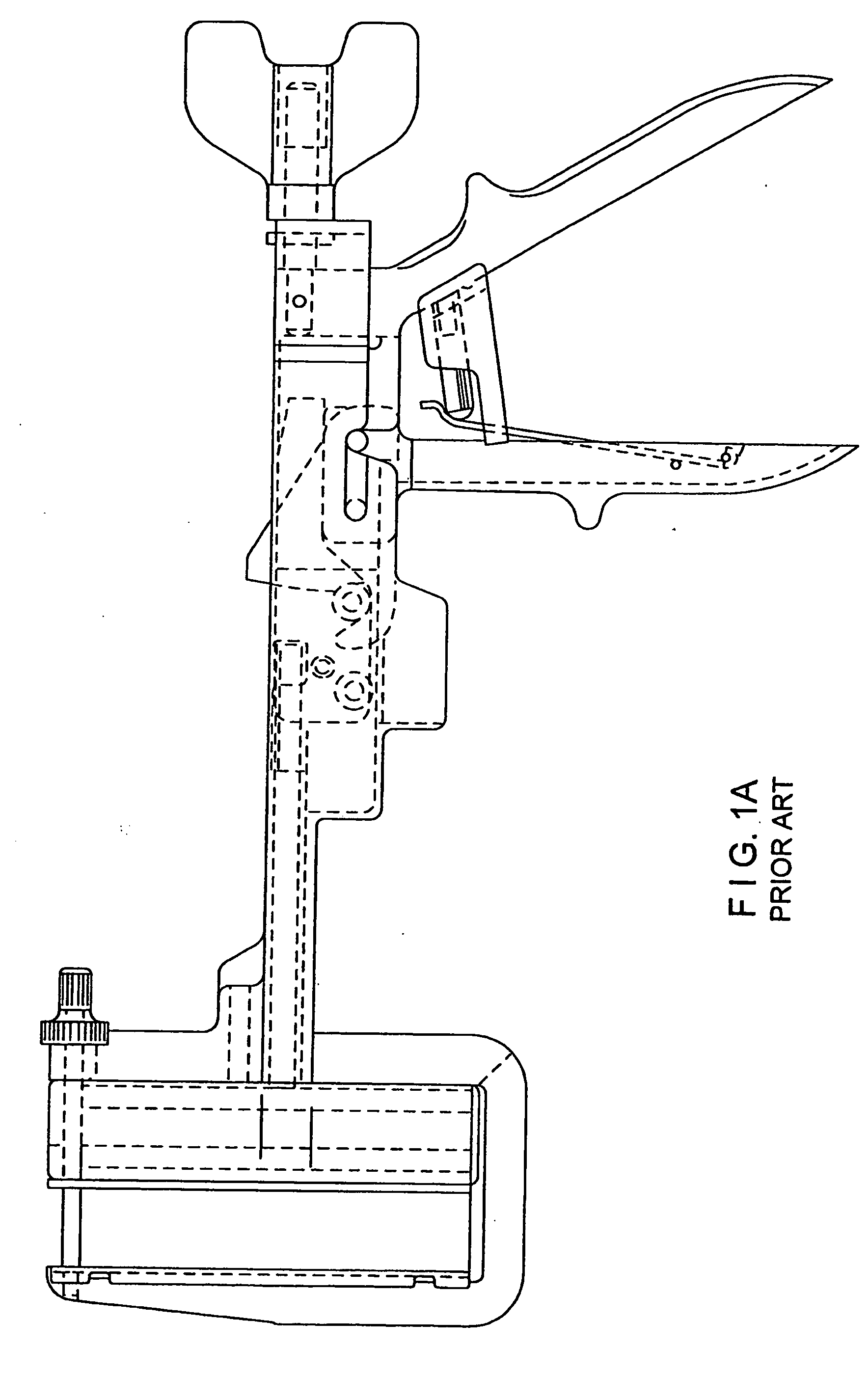
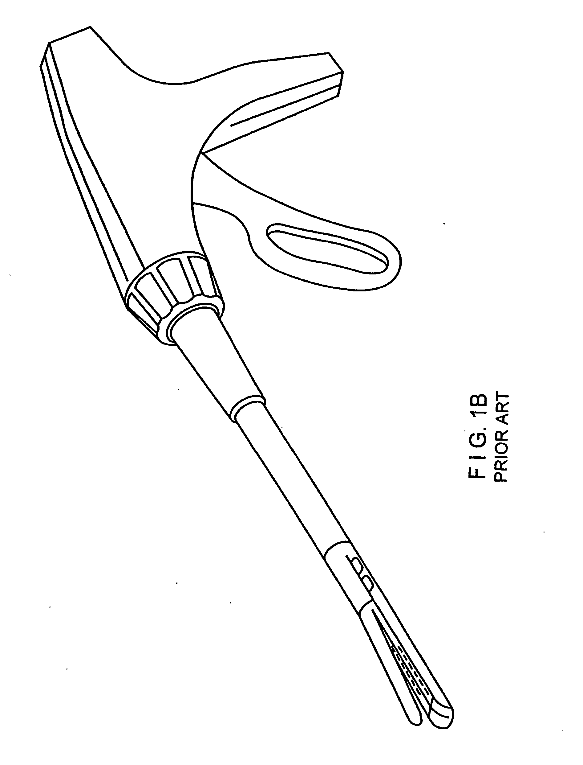
1(a) and 1(b), are difficult to maneuver, especially inside the patient's body.
Another problem with the foregoing surgical devices is that the devices may not be positionable satisfactorily within the patient's body.
For example, when a conventional device is employed to clamp, cut and staple a section of tissue immediately adjacent to an anal stump, it may be desirable to position the device, and to clamp, cut and staple a section of tissue, as close as possible to the anus—however, conventional devices may not be positionable as close to the anal stump as desired because the jaws of the surgical device, when in the open position, require a large space and are prevented from being satisfactorily positioned by tissue inside the patient's body and surrounding the anal stump.

Method used


Image

  • Surgical device
  • Surgical device
  • Surgical device

Examples


Embodiment Construction

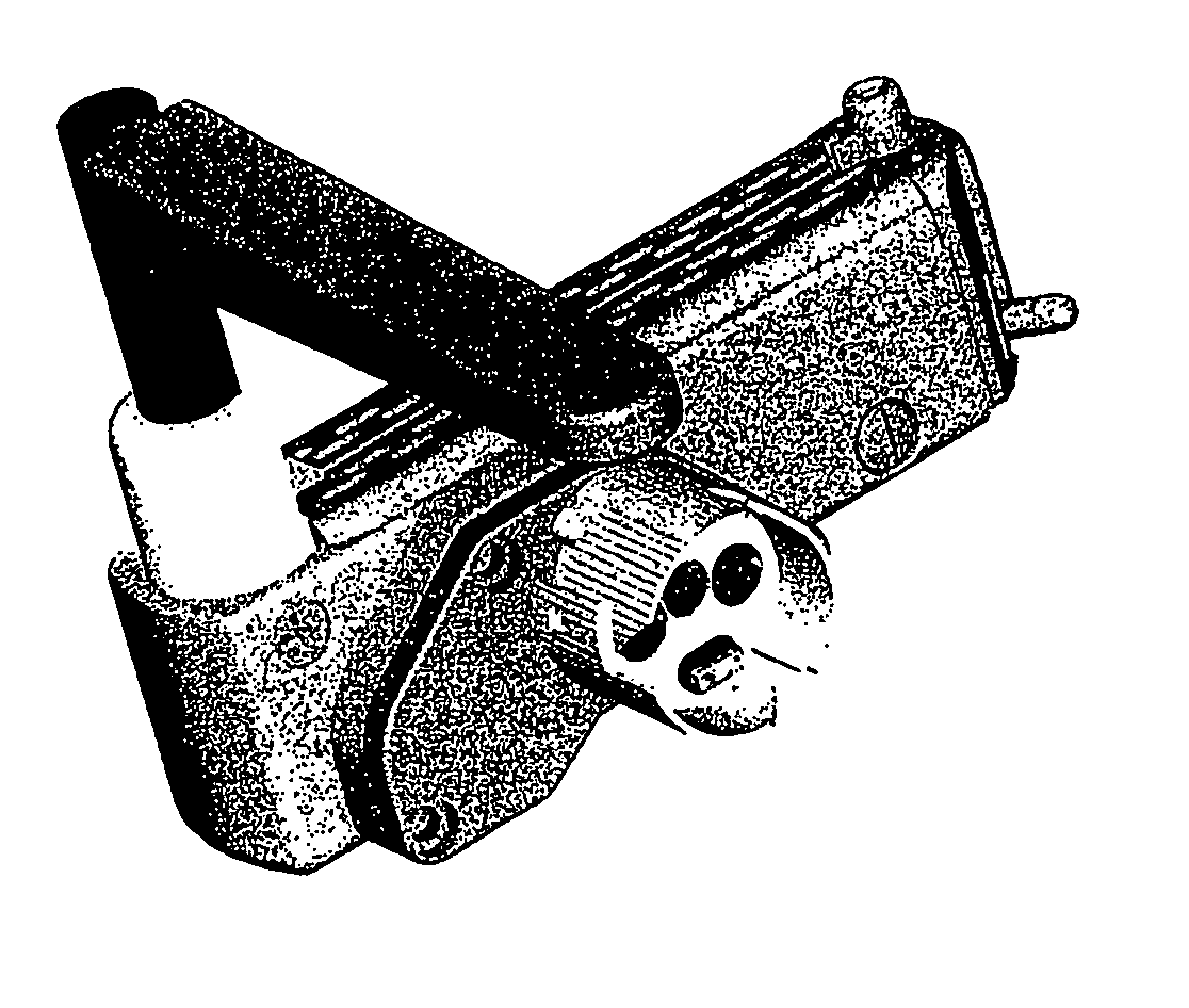
[0040] An example embodiment of a surgical device 11 according to the present invention is illustrated in FIGS. 3 to 7. Referring to FIGS. 3 and 4, an example embodiment of the surgical device 11, e.g., a clamping, cutting and stapling device, is illustrated. In this example embodiment, the surgical device 11 includes a second jaw 50 moveable relative to a first jaw 80. A first end 50a of second jaw 50 is mechanically coupled to a first end 80a of first jaw 80.

[0041]FIG. 3 is a perspective view that illustrates the surgical device 11 in an open position, wherein the second jaw 50 and the first jaw 80 are in contact with each other at their first ends 50a and 80a. In the open position, the first jaw 80 is maintained in a longitudinal plane defined by the x and y axes illustrated in FIG. 3, while the second jaw 50 is moved, e.g., swiveled, at least partially out of the longitudinal plane defined by the x and y axes. Specifically, the surgical device 11 is configured such that, in add...


PUM

PropertyMeasurementUnit
relative movementaaaaaaaaaa
rotationaaaaaaaaaa
rotation axisaaaaaaaaaa

Abstract

A surgical device includes a first jaw and a second jaw moveable relative to the first jaw between a first position, in which the first and second jaws are aligned within a plane, and a second position, in which the second jaw is in non-parallel correspondence to the plane. The surgical device may include a surgical member, e.g., a cutting and / or stapling element, disposed within the first jaw, and a second driver configured to cause relative movement of the surgical member in a direction parallel to the plane. The first and second jaws may include a camming arrangement that is configured to move the second jaw between the first and second positions. The camming arrangement may include a channel disposed along at least a portion of one or both of the first and second jaws, a ball bearing disposed within the channel.

Description

CROSS-REFERENCE TO RELATED APPLICATIONS [0001] The present application is related to U.S. patent application Ser. No. 09 / 510,923, filed on Feb. 22, 2000, now issued as U.S. Pat. No. 6,517,565 on Feb. 11, 2003, U.S. patent application Ser. No. 09 / 723,715, filed on Nov. 28, 2000, U.S. patent application Ser. No. 09 / 836,781, filed on Apr. 17, 2001, U.S. patent application Ser. No. 09 / 887,789, filed on Jun. 22, 2001, and U.S. Provisional Patent Application Ser. No. 60 / 337,544, filed on Dec. 4, 2001, U.S. patent application Ser. No. 10 / 309,532, filed on Dec. 4, 2002, U.S. patent application Ser. No. 10 / 094,051, filed on Mar. 8, 2002, each of which is expressly incorporated herein by reference in its entirety.FIELD OF THE INVENTION [0002] The present invention relates to a surgical device. More specifically, the present invention relates to a clamping, cutting and stapling device having a swivelable jaw. BACKGROUND INFORMATION [0003] The literature is replete with descriptions of surgical...

Claims


Application Information

Patent Timeline
Patent Type & Authority Applications(United States)
IPC IPC(8): A61B17/10
CPCA61B2017/2936A61B17/32A61B17/282A61B2017/2927A61B2017/00017A61B17/072A61B2017/2939A61B17/07207A61B2017/2933A61B2017/07214A61B2017/00199A61B2017/2944A61B17/068
Inventor WHITMAN, MICHAEL P.DATCUK, PETER T.
Owner TYCO HEALTHCARE GRP LP
Learn More