Image scanning device and multi-function device

Inactive Publication Date: 2007-02-01
BROTHER KOGYO KK
View PDF26 Cites 21 Cited by
  • Summary
  • Abstract
  • Description
  • Claims
  • Application Information

AI Technical Summary

Benefits of technology

[0009] The technique of the present invention utilizes the CIS and disposes the display device at

Problems solved by technology

Even when a less height is needed for the scanner, the image scanning devi

Method used


Image

  • Image scanning device and multi-function device
  • Image scanning device and multi-function device
  • Image scanning device and multi-function device

Examples


embodiments

(Embodiments)

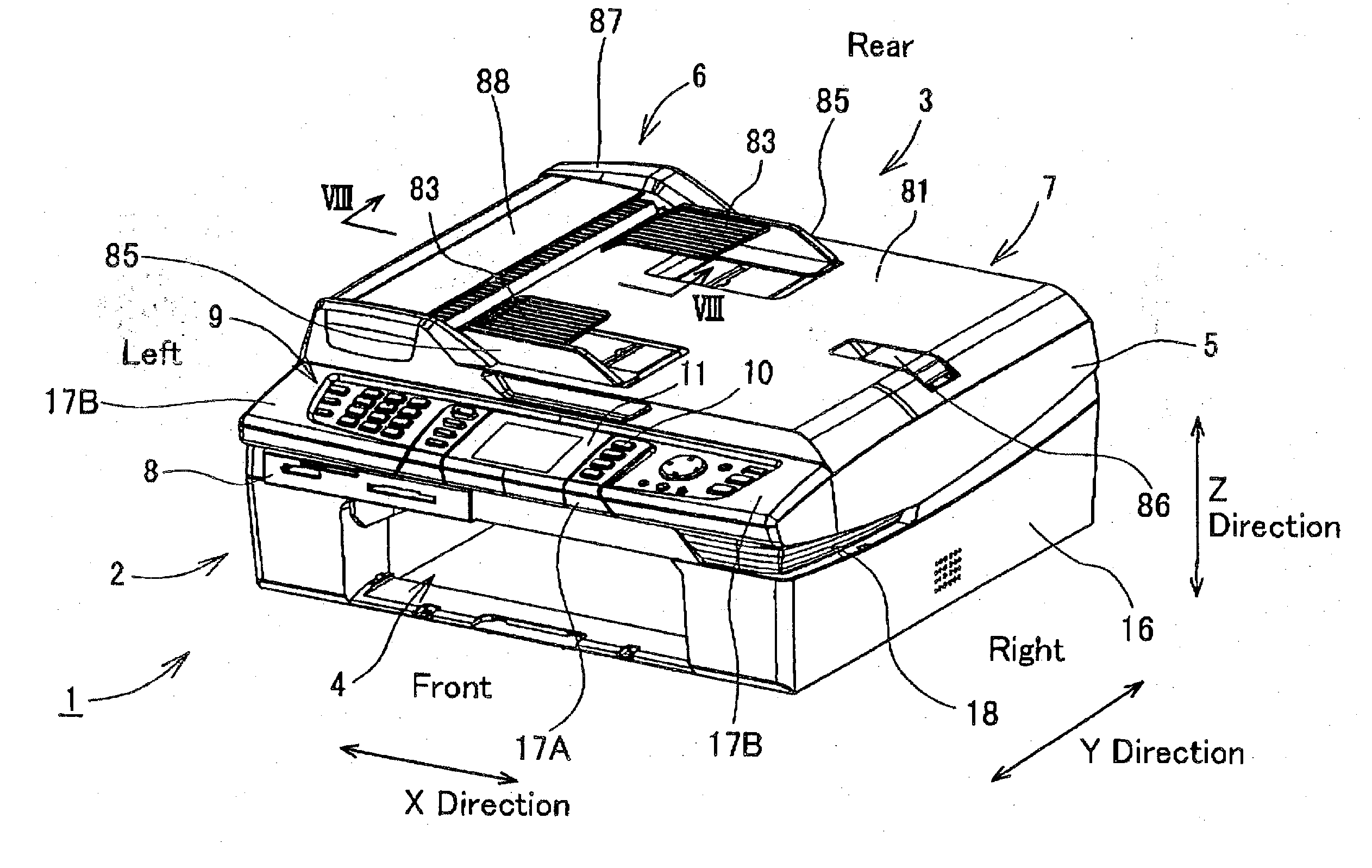
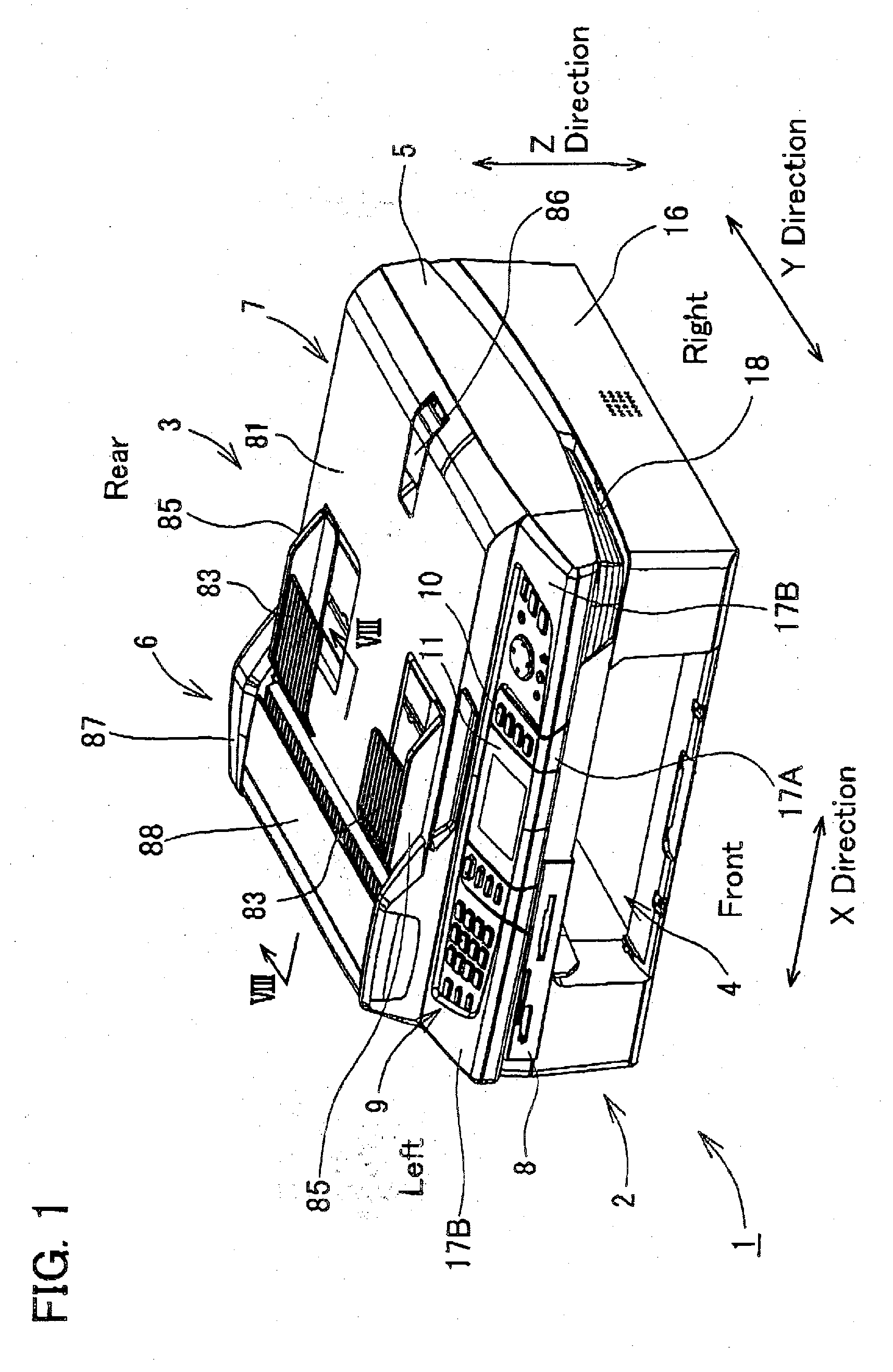
[0032] An embodiment of the present invention will now be described with reference to the drawings. FIG. 1 shows a perspective view of a multi-function device 1 of the present embodiment. The multi-function device 1 has a printer function, a scanner function, a copy function, and a fax function. The multi-function device 1 comprises a recording device 2 and a scanning device 3. The recording device 2 is disposed at a lower side, and the scanning device 3 is disposed at an upper side.

[0033] The multi-function device 1 can be connected with, for example, a computer (not shown). The multi-function device 1 prints an image on a print medium based on image data or document data output from the computer. The multi-function device 1 can also be connected with an external device such as a digital camera, etc. Image data output from the digital camera can be input to the multi-function device 1, and the multi-function device 1 can print onto printing paper the image data that h...


PUM


Abstract

An image scanning device is provided with a transparent plate, a contact image sensor, a scanning device casing, a cover member, and a display device. An image medium having an image to be scanned is placed on the transparent plate. The contact image sensor is disposed below the transparent plate, and scans the image of the image medium placed on the transparent plate. The scanning device casing houses the transparent plate and the contact image sensor. The cover member covers a top face of the transparent plate. The display device is capable of moving between a lying position and a standing position. In a state where the display device is positioned anywhere between the lying position and the standing position, a top end of the display device is lower than a top end of the cover member, and a bottom end of the display device is higher than a bottom end of the scanning device casing.

Description

CROSS-REFERENCE TO RELATED APPLICATION [0001] This application claims priority to Japanese Patent Application No. 2005-216242, filed on Jul. 26, 2005, the contents of which are hereby incorporated by reference into the present application. This application also claims priority to Japanese Patent Application No. 2005-216448, filed on Jul. 26, 2005, the contents of which are hereby incorporated by reference into the present application. BACKGROUND OF THE INVENTION [0002] 1. Field of the Invention [0003] The present invention relates to an image scanning device. Further, the present invention relates to a multi-function device having at least an image scanning function and an image recording function. The term ‘image’ in the present specification should be interpreted in the broadest sense, and includes words, diagrams, figures, colors, etc. or a combination thereof. [0004] 2. Description of the Related Art [0005] Image scanning devices are widely known. Most image scanning devices hav...

Claims


Application Information

Patent Timeline
IPC IPC(8): H04N1/04
CPCG03G15/5016H04N2201/0094H04N1/00411H04N1/00427H04N1/0044H04N1/00474H04N1/00482H04N1/00493H04N1/00496H04N1/00519H04N1/00525H04N1/00535H04N1/2104H04N1/2158H04N1/00387
Inventor IKENO, TAKAHIROMURAKI, MOTOHITO
Owner BROTHER KOGYO KK
Why Eureka
Try Eureka