Image forming apparatus

Inactive Publication Date: 2007-02-01
HEWLETT PACKARD DEV CO LP
View PDF4 Cites 7 Cited by
  • Summary
  • Abstract
  • Description
  • Claims
  • Application Information

AI Technical Summary

Benefits of technology

[0015] Additional aspects and / or advantages of the present invention will be set forth in part in the description which follows and, in part, will be obvious from the description, or may be learned by practice of the present invention.

Problems solved by technology

However, according to the conventional image forming apparatus 100 described above, there may be a problem that the developing part 110 is not easily removed from the installation part 122.

Method used


Image

  • Image forming apparatus
  • Image forming apparatus
  • Image forming apparatus

Examples


Embodiment Construction

[0025] Reference will now be made in detail to the embodiments of the present invention, examples of which are illustrated in the accompanying drawings, wherein like reference numerals refer to like elements throughout. The embodiments are described below in order to explain the present invention by referring to the figures.

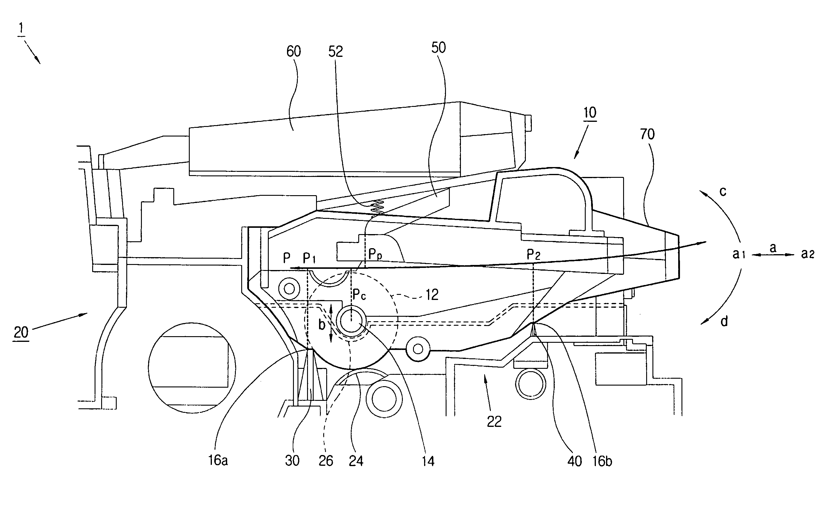
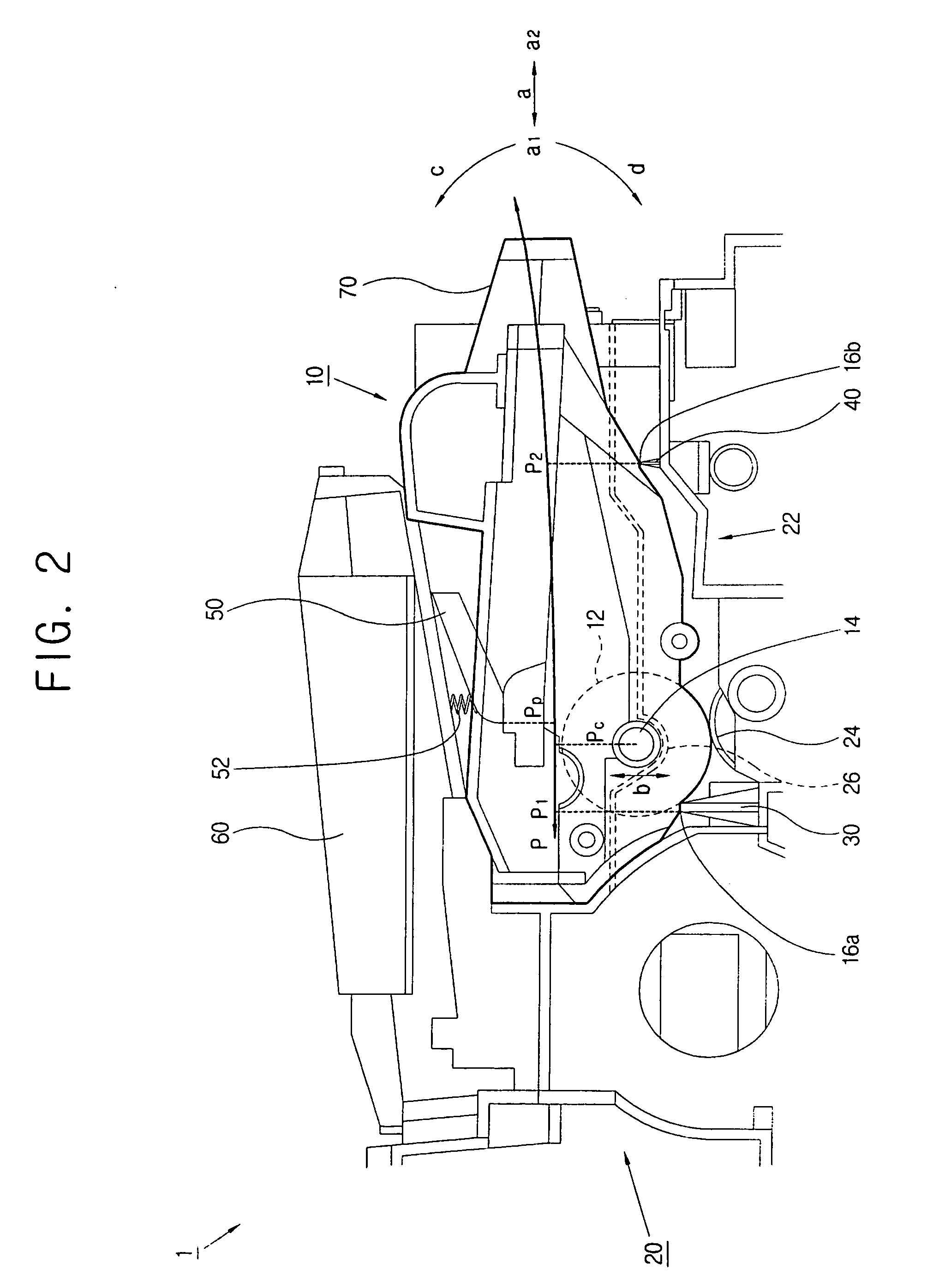
[0026]FIG. 2 is an exploded side view of an image forming apparatus according to an embodiment of the present invention. As shown in FIG. 2, an image forming apparatus 1 comprises a developing part 10, a main body 20 and a scanning unit 60. The developing part 10 comprises a developing process roller 12 to perform a developing process. The main body 20 comprises an installation part 22. The developing part 10 is detachably installed to the installation part 22. The scanning unit 60 may be provided at the main body 20 or at the developing part 10, but is shown provided at the main body 20. The scanning unit 60 comprises a light source such as a laser diode and an...


PUM


Abstract

An image forming apparatus includes a developing part having a developing process roller and a position restricting protrusion; a main body having an installation part to install the developing part and a roller driving part driving the developing part; a position restricting groove part to engage the position restricting protrusion so that the developing process roller engages the roller driving part when the developing part is installed; a first rotation supporting part between the installation and developing parts to be positioned at a first position when the developing part is installed to the installation part, and supporting the developing part so that the position restricting protrusion detaches from the position restricting groove part; and a second rotation supporting part between the installation and developing parts to be positioned at a second position and supporting the developing part so that the position restricting protrusion detaches from the position restricting groove part.

Description

CROSS-REFERENCE TO RELATED APPLICATION [0001] This application claims the benefit of Korean Patent Application No. 2005-67625, filed on Jul. 26, 2005 in the Korean Intellectual Property Office, the disclosure of which is incorporated herein by reference. BACKGROUND OF THE INVENTION [0002] 1. Field of the Invention [0003] Aspects of the present invention relate to an image forming apparatus, and more particularly, to an image forming apparatus in which a developing part is conveniently installed to and removed from a main body. [0004] 2. Description of the Related Art [0005] Generally, an image forming method of an image forming apparatus includes an electrophotographic method. In the electrophotographic method, an image is developed by applying developer to an electrostatic latent image formed on a photosensitive element by a potential difference and transferred to a printing paper to be formed. Another image forming method is an inkjet method, where an image is formed by dischargin...

Claims


Application Information

Patent Timeline
IPC IPC(8): G03G21/18
CPCG03G2221/163G03G21/1853G03G2221/1815G03G2221/1654G03G15/06
Inventor JEONG, YOO-HUNGCHOI, JAI-IL
Owner HEWLETT PACKARD DEV CO LP
Why Eureka
Try Eureka