Type Of Constant Velocity Universal Joint With The Spline Slip Structure

Active Publication Date: 2019-03-14
ZHEJIANG CFMOTO POWER CO LTD
View PDF0 Cites 1 Cited by
  • Summary
  • Abstract
  • Description
  • Claims
  • Application Information

AI Technical Summary

Benefits of technology

The purpose of this invention is to create a type of universal joint that allows for easy removal of the shaft from the sleeve. This is done using a spline slip structure.

Problems solved by technology

The steel wire retaining ring is arranged on the constant velocity universal joint with the spline slip structure, and it can be moved in the radial direction under the free state; so it is very difficult for maintenance and disassembling, and it is possible to cut off the retaining ring before it can be removed, or even the retaining ring is unable to be removed normally.
Therefore, how to provide a type of constant velocity universal joint with the spline slip structure to facilitate removing the spline shaft from the star-shaped sleeve is technical defect which urgently need to be solved for those skilled in the art.

Method used


Image

  • Type Of Constant Velocity Universal Joint With The Spline Slip Structure
  • Type Of Constant Velocity Universal Joint With The Spline Slip Structure
  • Type Of Constant Velocity Universal Joint With The Spline Slip Structure

Examples


Embodiment Construction

[0018]To make the purpose, technical scheme and advantages of the embodiment of the present invention more clear, technical scheme of the embodiment of the present invention is clearly and completely described in the following combined with the accompanying drawings of the embodiment of the present invention; obviously, the embodiment of the present invention is a part of the embodiments, not all of the embodiments of the present invention. Based on the embodiment of the present invention, all other embodiments Which the ordinary technical personnel in the art obtain at the premise of without giving creative labor are also deemed to fall into the protection scope of the present invention.

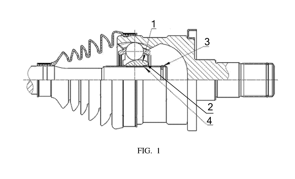
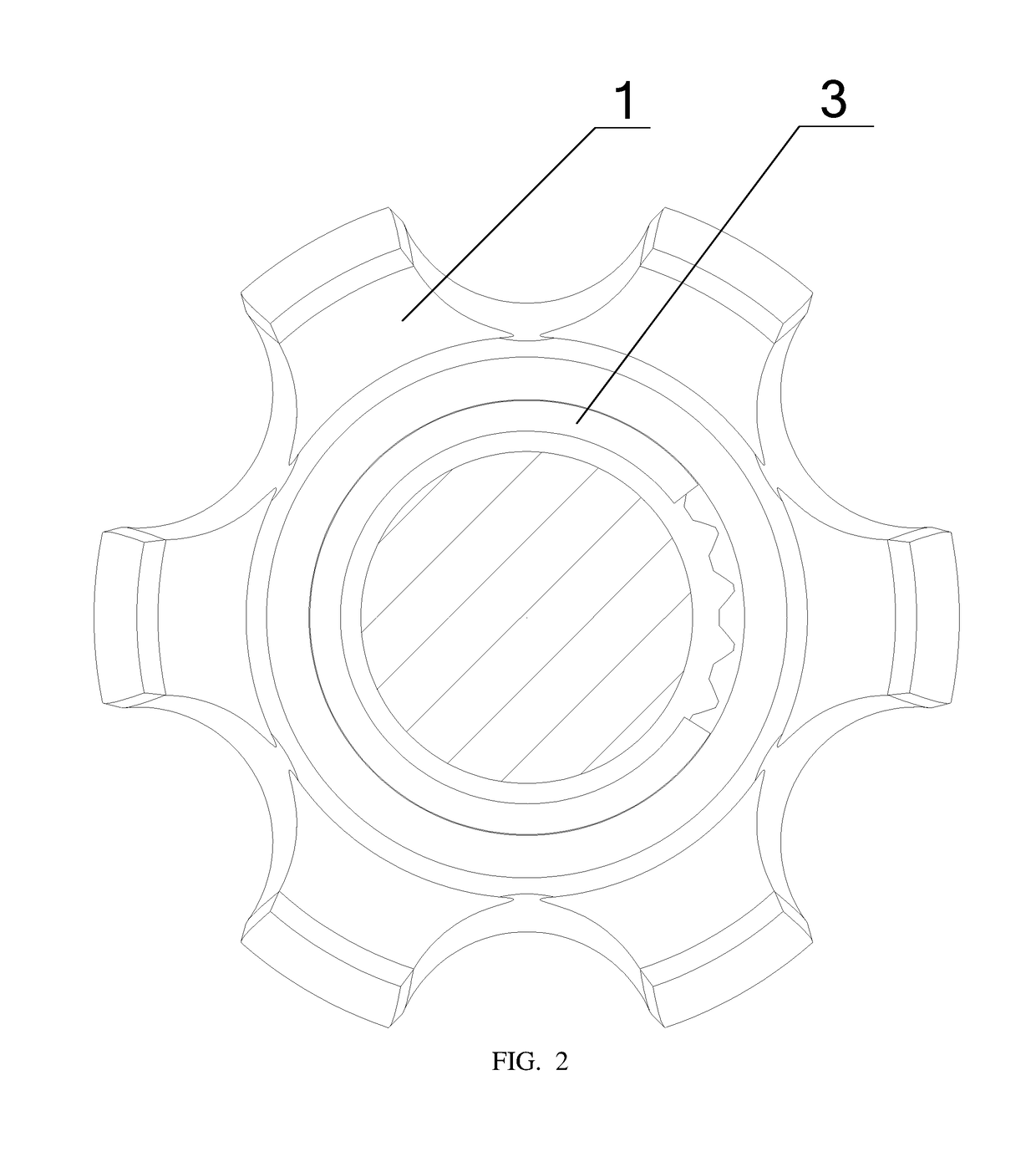
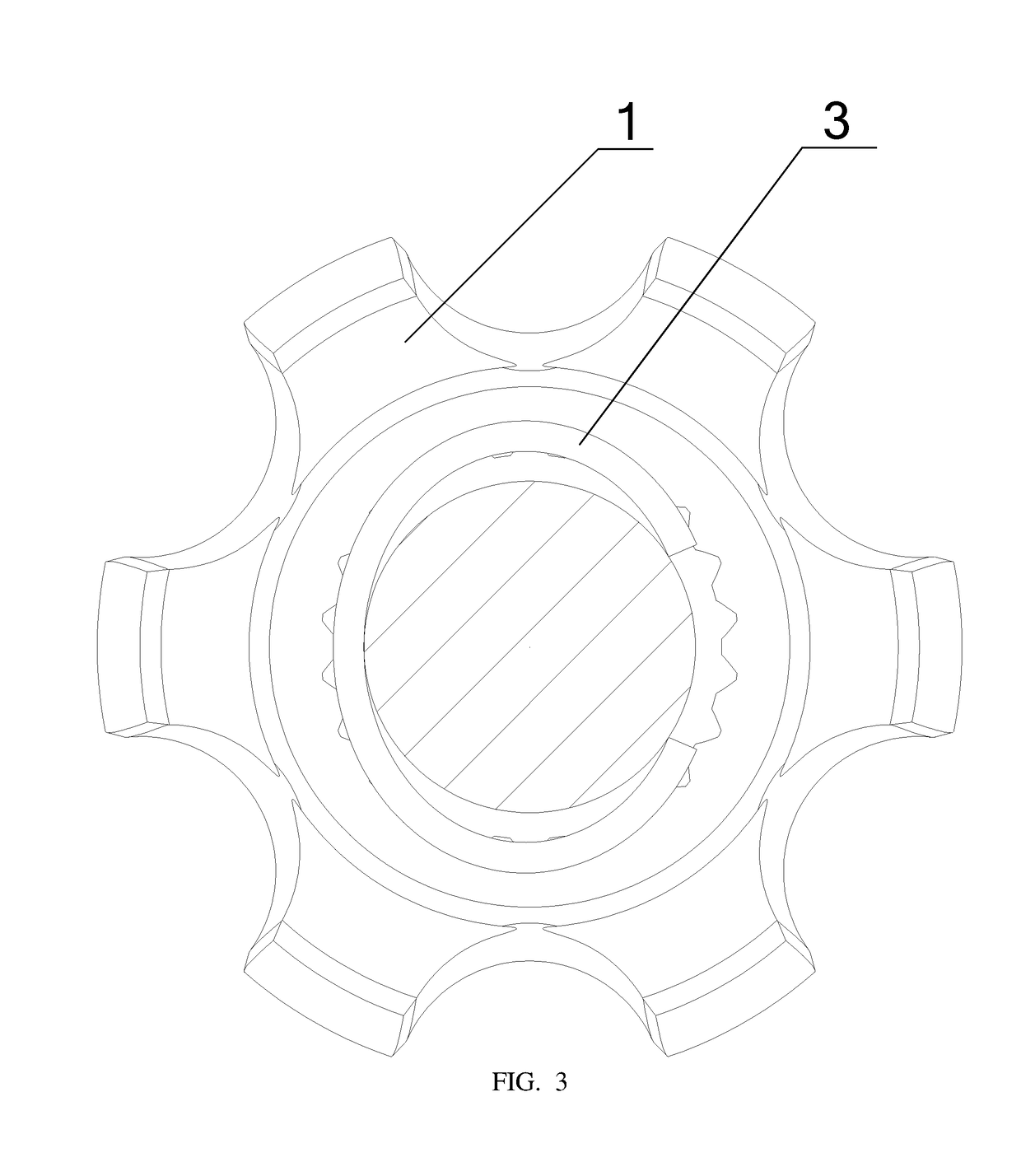
[0019]Referring to FIGS. 1-3. FIG. 1 is the schematic view showing the structure of the steel wire retaining ring being arranged on the constant velocity universal joint with the spline slip structure provided by the embodiment of the present invention. FIG. 2 is the side schematic view showing the ...


PUM


Abstract

A type of constant velocity universal joint has the spline slip structure, including the steel wire retaining ring and the star-shaped sleeve which are both mounted on a common axis, and the steel wire retaining ring limiting device. The said steel wire retaining ring limiting device is a groove arranged on the said star-shaped sleeve and used for holding the said steel wire retaining ring. The said steel wire retaining ring may be elliptic or circular. The movement in the radial direction of the steel wire retaining ring will be limited by the groove on the star-shaped sleeve and there occurs a certain contraction, in addition to appropriate the chamfer angle of the groove, so it is very convenient to remove the spline shaft from the star-shaped sleeve.

Description

CROSS-REFERENCE TO RELATED U.S. APPLICATION(S)[0001]None.FIELD OF THE INVENTION[0002]The present invention relates to the technical field of universal joint, particularly to a type of constant velocity universal joint with the spline slip structure.BACKGROUND OF THE INVENTION[0003]The steel wire retaining ring is arranged on the constant velocity universal joint with the spline slip structure, and it can be moved in the radial direction under the free state; so it is very difficult for maintenance and disassembling, and it is possible to cut off the retaining ring before it can be removed, or even the retaining ring is unable to be removed normally.[0004]Therefore, how to provide a type of constant velocity universal joint with the spline slip structure to facilitate removing the spline shaft from the star-shaped sleeve is technical defect which urgently need to be solved for those skilled in the art.BRIEF SUMMARY OF THE INVENTION[0005]In view of this, the purpose of the present inv...

Claims


Application Information

Patent Timeline
IPC IPC(8): F16D3/2245
CPCF16D3/2245F16D2003/22313F16D2003/22309F16D2003/22326F16D2300/12F16D2250/0084F16D3/06F16D3/223Y10T403/7033
Inventor CHENG, FUYINGKUANG, ZHENXIANGJIAJUN, LI
Owner ZHEJIANG CFMOTO POWER CO LTD
Why Eureka
Try Eureka