Battery Latch Structure

Active Publication Date: 2008-10-16
HYTERA COMM CORP
View PDF0 Cites 5 Cited by
  • Summary
  • Abstract
  • Description
  • Claims
  • Application Information

AI Technical Summary

Benefits of technology

[0006]The present invention is to solve issues such as complicated operation and poor reliability involved in the conventional battery latch structures, and to provide a new battery latch structure, which offers secure connection between the battery and the mobile communication device, and more convenient removing of the battery. To solve the foregoing issues, the present invention provides a battery latch structure, wherein a battery slot for receiving a battery is located on the main body, a first end of said battery is latched to a first end of said slot through a first clamp structure, and a second end of said battery is latched to a second end of said slot through a second clamp structure. The second clamp structure includes a second fixed clamp located on the left and right sides of the second end of said slot, and a battery latch, a spring and two battery lock members located at the second end of said battery. The battery latch is located at the second end of the battery and may be slid upwards and downwards to be moveably connected with the two battery lock members. The spring is located between the two battery lock members. The said spring can push the two battery lock members protruding leftwards and rightwards respectively to insert into the second clamp. The said battery latch can be moved upwards by the action of outside force, to release the two battery lock members from the second clamp.
[0007]This structure facilitates users to easily attach or remove the battery. The present battery latch structure is simple in design, to ensure a secure connection between the battery and the main body, and facilitates the operation of the users, further helps to prevent said injury.
[0008]Advantageously, the said two battery lock members are arranged symmetrically, and each battery lock member includes a vertical part and a horizontal part integrated with the vertical part, wherein the vertical part is latched to the battery latch to convert the upward and downward movement of the battery latch to the leftward and rightward movement of the battery lock member, thereby cause the horizontal part of the battery lock member may be stretched or retracted leftwards and rightwards to be inserted into or released from the second clamp. This method could result in more reliable connection between the battery and the main body.

Problems solved by technology

However, this kind of design has some disadvantages.
Since the battery must be slid horizontally while the battery latch must be pushed downwards when removing the battery, the operation is complicate and inconvenient.
Additionally, sliding the battery horizontally may cause your fingers injured.
Moreover, the sliding connection between the main body and the battery may be over-tight or over-loose caused by the design and the usage, which shall affect the use of product.

Method used


Image

  • Battery Latch Structure
  • Battery Latch Structure
  • Battery Latch Structure

Examples


Embodiment Construction

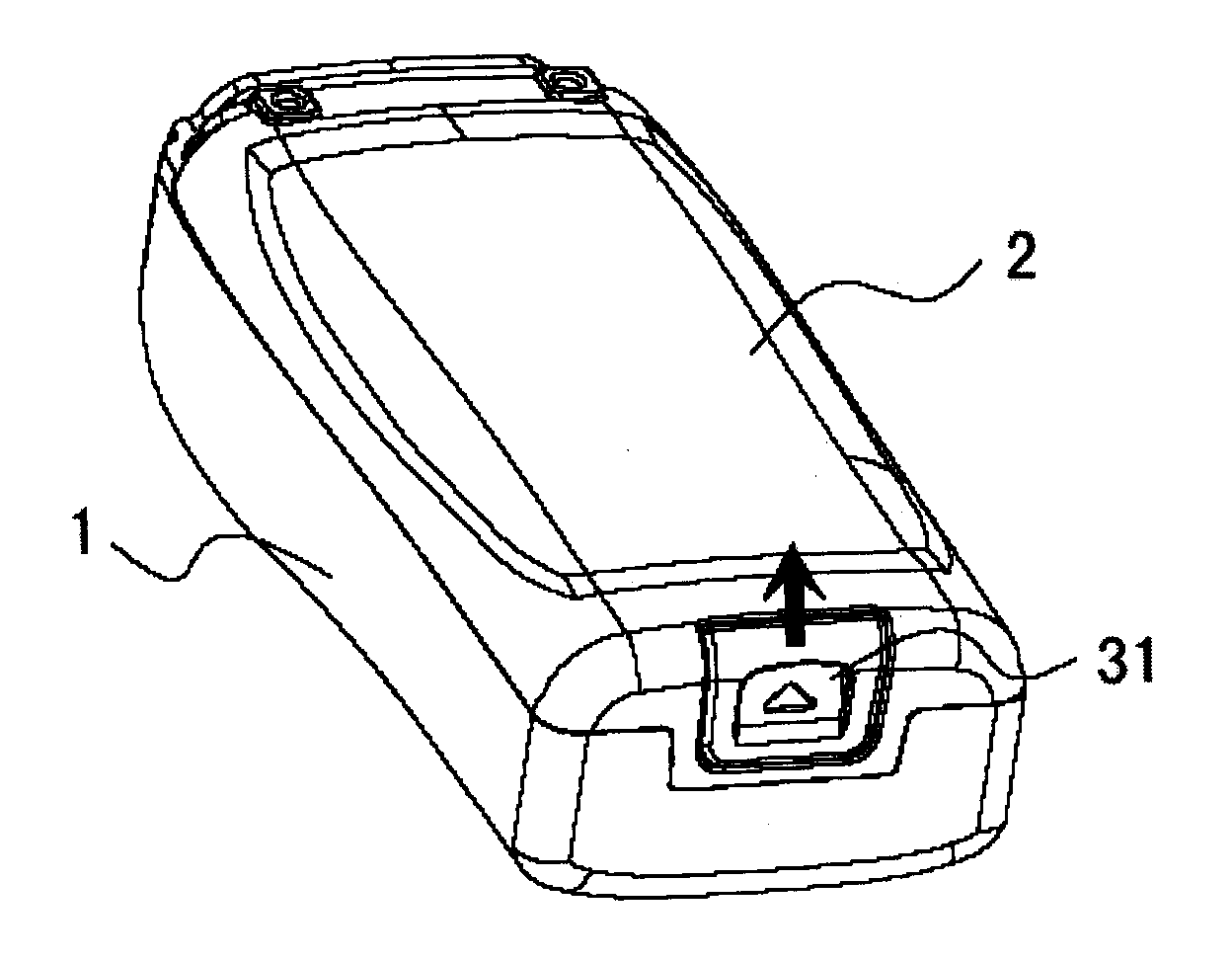
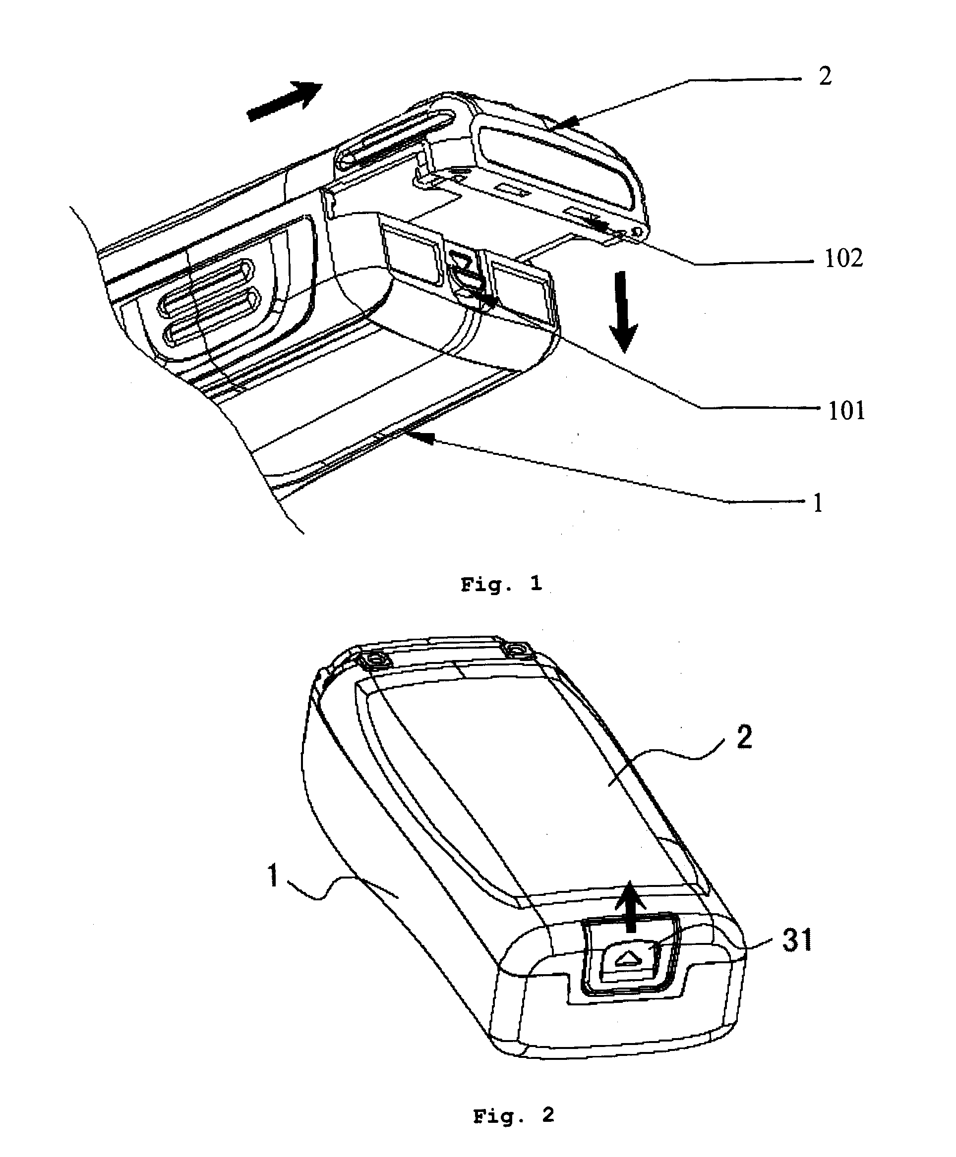
[0020]To make the technical issues that to be solved by the present invention, the technical solutions and effects more explicit, the detailed description of the present invention is given below combined with the drawings and embodiments. A preferred embodiment of the present invention is shown in FIGS. 2 to 9, wherein the device is a two-way radio, and a battery 2 is attached on the main body 1 through a battery latch structure.

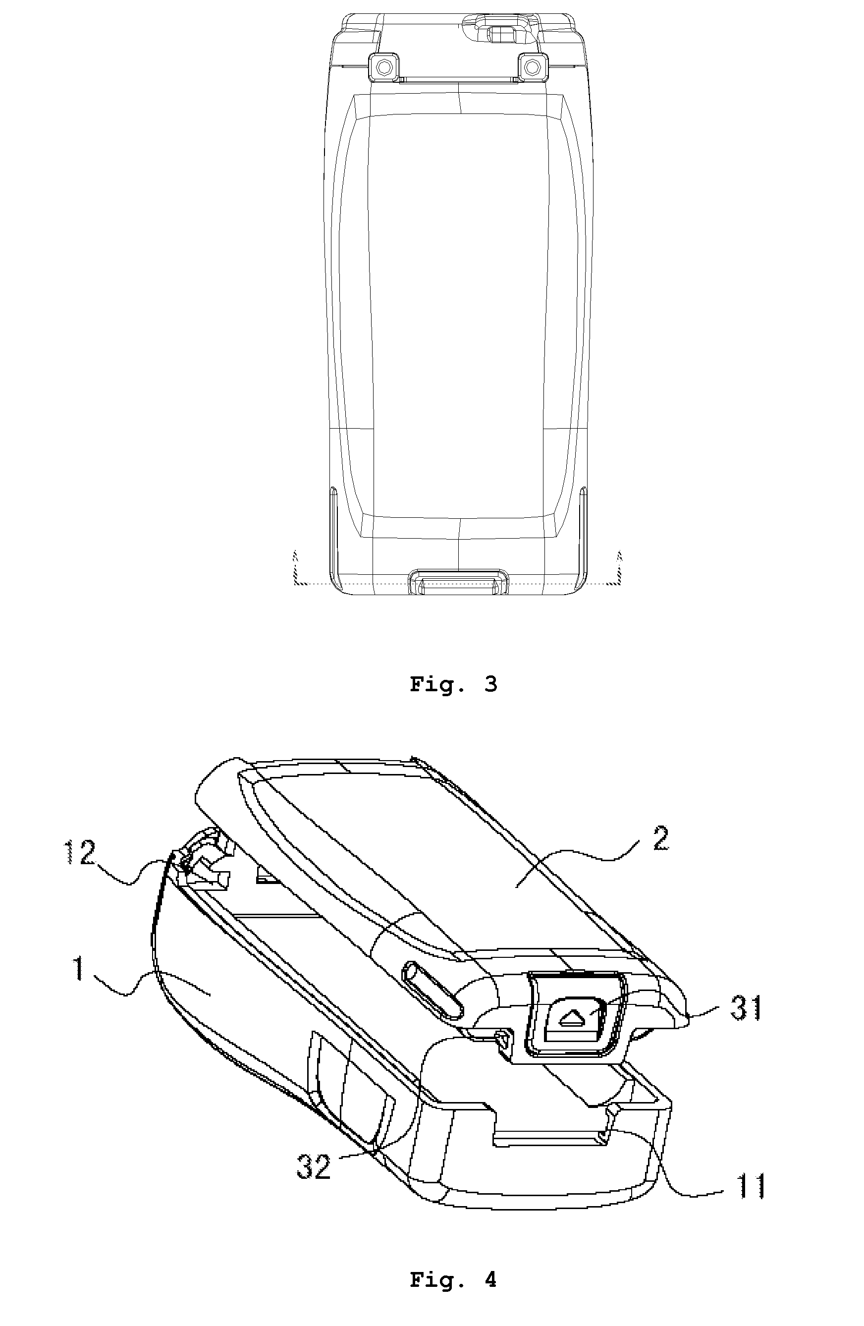
[0021]As shown in FIGS. 2 to 4, in this preferred embodiment of the present invention, a recessed slot used for attaching the battery is located on the main body 1. When the battery is slid into the slot, it is integrated with the main body to form one unit. A first end of the battery (i.e. the top left end shown in FIG. 4) is latched to a first end of the slot through a first clamp structure, and a second end of the battery (i.e. the bottom right end shown in FIG. 4) is latched to a second end of said slot through a second clamp structure. As shown in FIG. ...


PUM


Abstract

The present invention discloses a battery latch structure, wherein a battery slot for receiving a battery is located on the main body, a first end of said battery is latched to a first end of said slot through a first clamp structure, and a second end of said battery is latched to a second end of said slot through a second clamp structure. The second clamp structure includes a second fixed clamp located on the left and right sides of the second end of said slot, and a battery latch, a spring and two battery lock members located at the second end of said battery. The battery latch is located at the second end of the battery and may be slid upwards and downwards to be moveably connected with the two battery lock members. The spring is located between the two battery lock members. The said spring can push the two battery lock members protruding leftwards and rightwards respectively to insert into the second clamp. The said battery latch can be moved upwards by the action of outside force, to release the two battery lock members from the second clamp. The advantages of the present invention are simple in structure and convenient for operation.

Description

CROSS REFERENCE TO RELATED PATENT APPLICATION [0001]This patent application claims the priority of the Chinese patent application No. 200720119450.8, filing date of Apr. 11, 2007.TECHNICAL FIELD OF THE INVENTION [0002]This invention refers to a battery latch structure between a battery and a main body of a device which is supplied by battery, and more particularly to such a battery latch structure for mobile communication devices such as two-way radio.BACKGROUND OF THE INVENTION [0003]Mobile communication devices such as two-way radio, mobile phone, have become an inevitable part in our daily life. Since these devices are frequently applied to mobile use, higher quality and durability are required for these devices.[0004]Generally speaking, such mobile communication devices as two-way radio or mobile phone are mainly composed of a main body of the device and a battery. Slot locates on the two sides of the main body, for users to slide battery into and then attach the battery. Then t...

Claims


Application Information

Patent Timeline
IPC IPC(8): H01M2/10H01R13/00
CPCH04M1/0262
Inventor GONG, GAOCHAO
Owner HYTERA COMM CORP
Why Eureka
Try Eureka