
Cap with conforming ear band

a cap and ear band technology, applied in the field of all-weather caps with ear protection, can solve the problems of compromising the utility of the cap, limiting or compromising the utility of the band, and affecting the comfort of the cap

Inactive Publication Date: 2007-02-15
STONE STEVEN R
View PDF25 Cites 9 Cited by
  • Summary
  • Abstract
  • Description
  • Claims
  • Application Information

AI Technical Summary

Benefits of technology

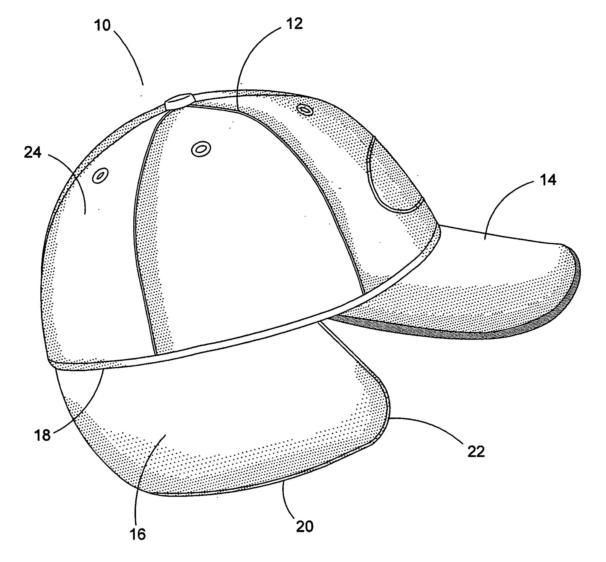
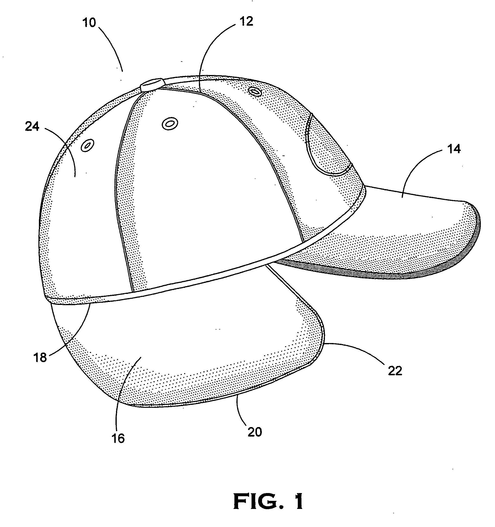
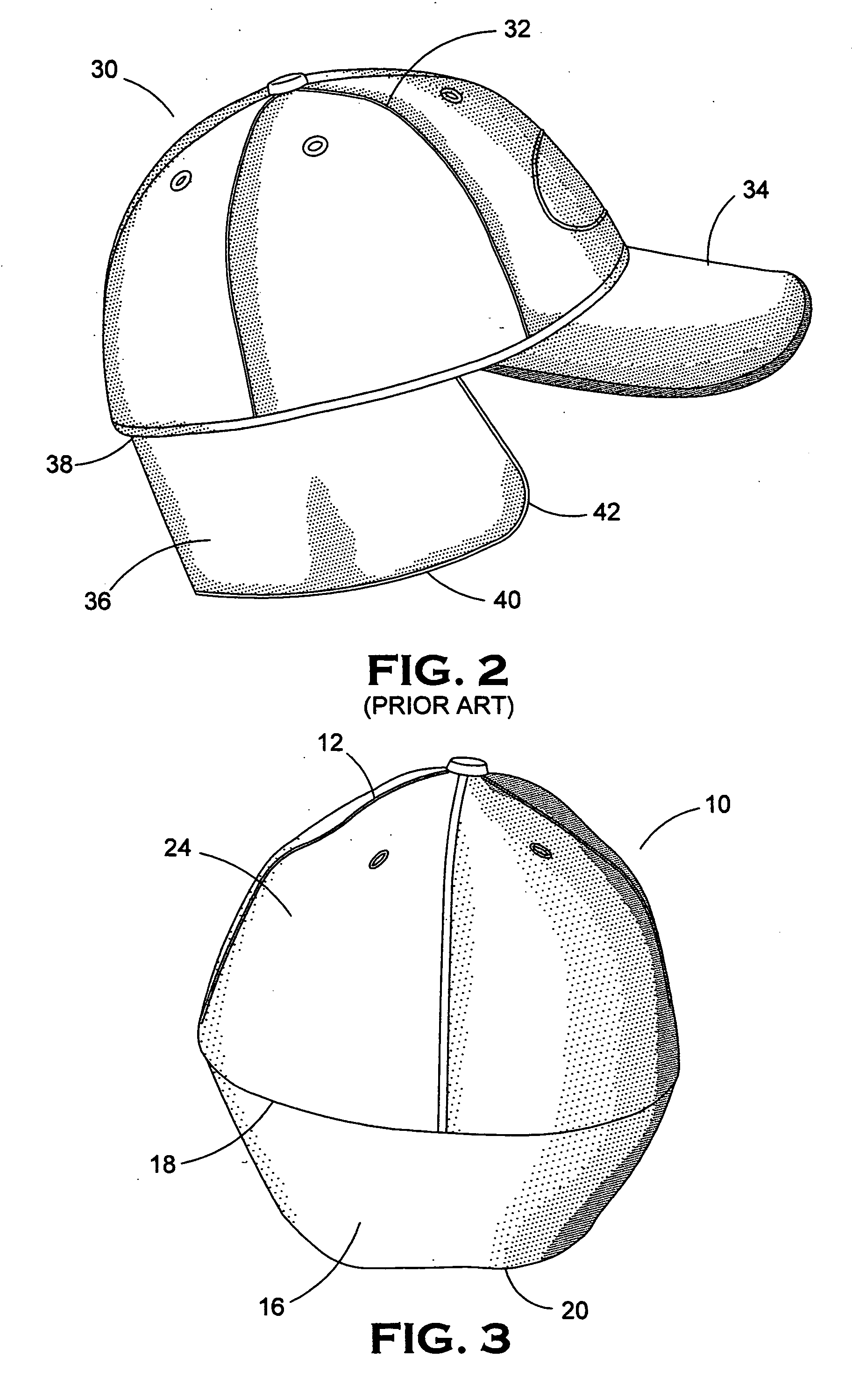
[0014] The present invention is an improved multi-sized cap with ear protection. The crown of the cap is constructed from several gores. A bill is centered on the seam of two of the gores and partially overlaps a gore to either side of those two. A single ear protecting band is attached to the interior of the base of the crown. This band starts just to the rear of the bill on one side, wraps around the back, and ends at the same location on the opposite side. The edge of the ear protecting band opposite the one attached to the crown is shorter than the edge attached to the crown. This causes the cap to form to the wearer's head by cupping under the ears and conforming more closely to the ears. Conversely, when the ear protecting band is folded into the crown, it tapers and fits the interior of the crown and avoids bunching. A biaxially elastic band circumscribes the inside of the crown and ear band with the ear band in the down position.
[0015] Accordingly, it is a primary objective of this invention to improve the fit of a cap having ear protection. The cap should conform more closely to the wearer's head and have less tendency to easily blow off in the wind.
[0016] It is a further objective of this invention to improve the compactness of a cap having ear protection when the ear protecting component is retracted.
[0018] It is another objective of this invention to protect forward areas of the wearer's face from the cold without obstructing the wearer's peripheral vision.
[0019] It is a further objective of this invention to provide an all weather cap that features an ear warming band which can benefit the wearer in cold temperatures, and yet, upon retraction of the ear warming band, the cap is still lightweight for warm temperature comfort.

Problems solved by technology

Although a variety of prior art caps can be found that feature an ear protection band, they generally also include features that limit or compromise the utility of the band.
This compromises the cap's utility in warmer weather.
A heavily insulated cap will be uncomfortable at that point.

Method used


Image

  • Cap with conforming ear band
  • Cap with conforming ear band
  • Cap with conforming ear band

Examples


Embodiment Construction

[0030] The following discussion illustrates only some of the possible configurations claimed in this invention and should not be interpreted as limiting the scope of any claims set forth in this utility application. FIG. 1 shows an embodiment of a cap 10 of the present invention. The cap 10 has dome shaped crown 12. A bill 14 is attached along the lower rim 18 of the cap. The cap in this embodiment has a fairly typical construction in its crown 12 in that it is comprised of several gores 24. These gores 24 have three sides. Two of the sides of the gores 24 are curved to allow several gores 24 to combine and form the domed crown 12, while the third side is relatively straight and forms a section of the rim 18 of cap 10. The bill 14 attaches to the lower rim 18 and is centered on a seam between two gores 24 of cap 10 and runs the entire width of those two gores 24, partially overlapping a gore 24 on each side. This is a fairly common construction in this field or art. In addition to t...


PUM


Abstract

An improved self adjusting cap for all weather use is disclosed. The improvement lies in the modified attached ear protecting band. The band has an upper edge attached to the crown and a shorter lower edge generally parallel to the upper edge. The lower edge has a shorter linear length than the upper edge so the band more closely conforms to the head of the wearer. Also, the band conforms to the head of the wearer when folded up into the cap without any bunching of material. Additionally, the two forward edges running from the upper edge to the lower edge have an arcuate shape which allows more of the face of the wearer to be protected without obstructing the peripheral vision of the wearer.

Description

BACKGROUND OF THE INVENTION [0001] 1. Field of The Invention [0002] This invention relates generally to an all-weather cap with ear protection. More specifically, it relates to self sizing cap having a crown constructed from multiple gores and having a bill, an elastic band around its lower rim, and an ear covering flap foldably extending from the opening. [0003] 2. Description of The Related Art [0004] In general, caps in the art are constructed from cloth gores which are triangular in shape, having a base and two sides extending from the base to meet at a point. Several gores, usually six, are sewn together along these sides in a closed circle fashion with the points of the gores coming together in the same spot. The result is a dome shape with its opening circumscribed by the base of the triangular gores. A bill is attached to this dome and is usually centered on a seam between two gores with the attached edge of the bill extending slightly past those two gores to contact, and be...

Claims


Application Information

Patent Timeline
IPC IPC(8): A42B1/06
CPCA42B1/22A42B1/066A42B1/0186A42B1/06
Inventor STONE, STEVEN R.
Owner STONE STEVEN R
Learn More