
Ski boot sole, disengageable ski binding and combination thereof

a technology of ski boot soles and ski boot soles, which is applied in the field of ski boot soles and the combination of ski boot soles and ski boot bindings to achieve the effect of ensuring disengaging and elasticity behavior and good

Inactive Publication Date: 2007-02-15
MARKER DEUTLAND +2
View PDF12 Cites 2 Cited by
  • Summary
  • Abstract
  • Description
  • Claims
  • Application Information

AI Technical Summary

Benefits of technology

[0013] It should be emphasized here that the rear sole holders, according to a preferred embodiment of the invention, can be disengaged only in the vertical direction, i.e. by forces which try to raise up the heel region of the boot vertically from the standing and / or carrying plate. Accordingly, there is no possibility of any displacements between the sole and standing and / or carrying plate in the heel region if disruptive forces give rise to a torque between the boot and ski in respect of the vertical axis.
[0015] According to a quite particularly preferred embodiment of the invention, the standing and / or carrying plate is assigned a torque support by means of which torques which act on the standing and / or carrying plate in respect of a transverse plate axis are converted into torques in respect of the vertical axis, and a moment which assists further rotation of the standing and / or carrying plate about the vertical axis is produced as soon as the standing and / or carrying plate has left a central position or a central position region. This makes it possible to allow for the fact that torsional loading of the shin and of the ankles and knee joints are to be reduced when the leg is subjected to additional stressing by further forces such as those which typically arise when the skier falls in the forward or rearward direction. Because of the abovementioned torque support, the disruptive forces which are responsible for further stressing are thus used in order to reduce the resistance to rotation which counteracts rotation of the standing and / or carrying plate about the vertical axis, with the result that a rotary displacement of the standing and / or carrying plate which unlocks the front boot or sole holders, and thus release of the boot, are achieved relatively easily.

Problems solved by technology

This is achieved, in the first instance, in that rotary movements of the standing and / or carrying plate about the vertical axis which are caused by disruptive forces, on account of the first and second latching devices being separate from one another and of the initially maintained locking of the front boot and / or sole holders, cannot result in any play, in particular clearance for rotation, of the boot sole relative to the standing and / or carrying plate.

Method used


Image

  • Ski boot sole, disengageable ski binding and combination thereof
  • Ski boot sole, disengageable ski binding and combination thereof
  • Ski boot sole, disengageable ski binding and combination thereof

Examples


Embodiment Construction

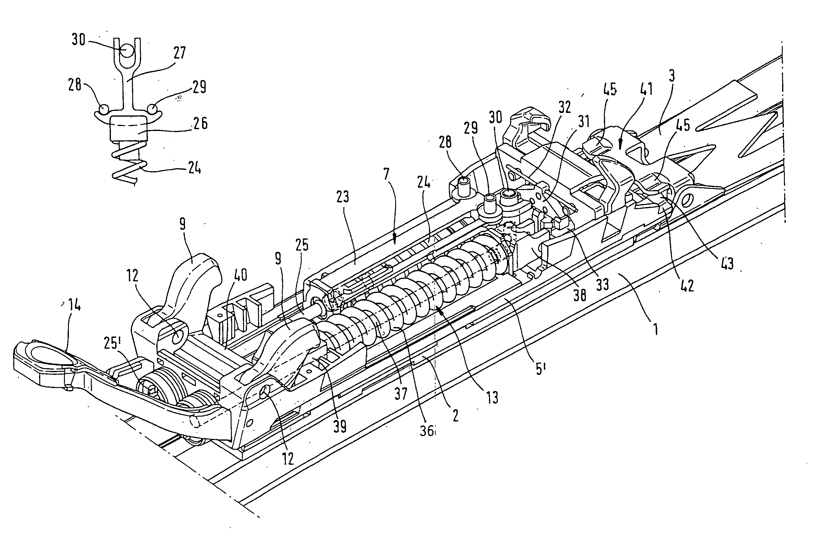
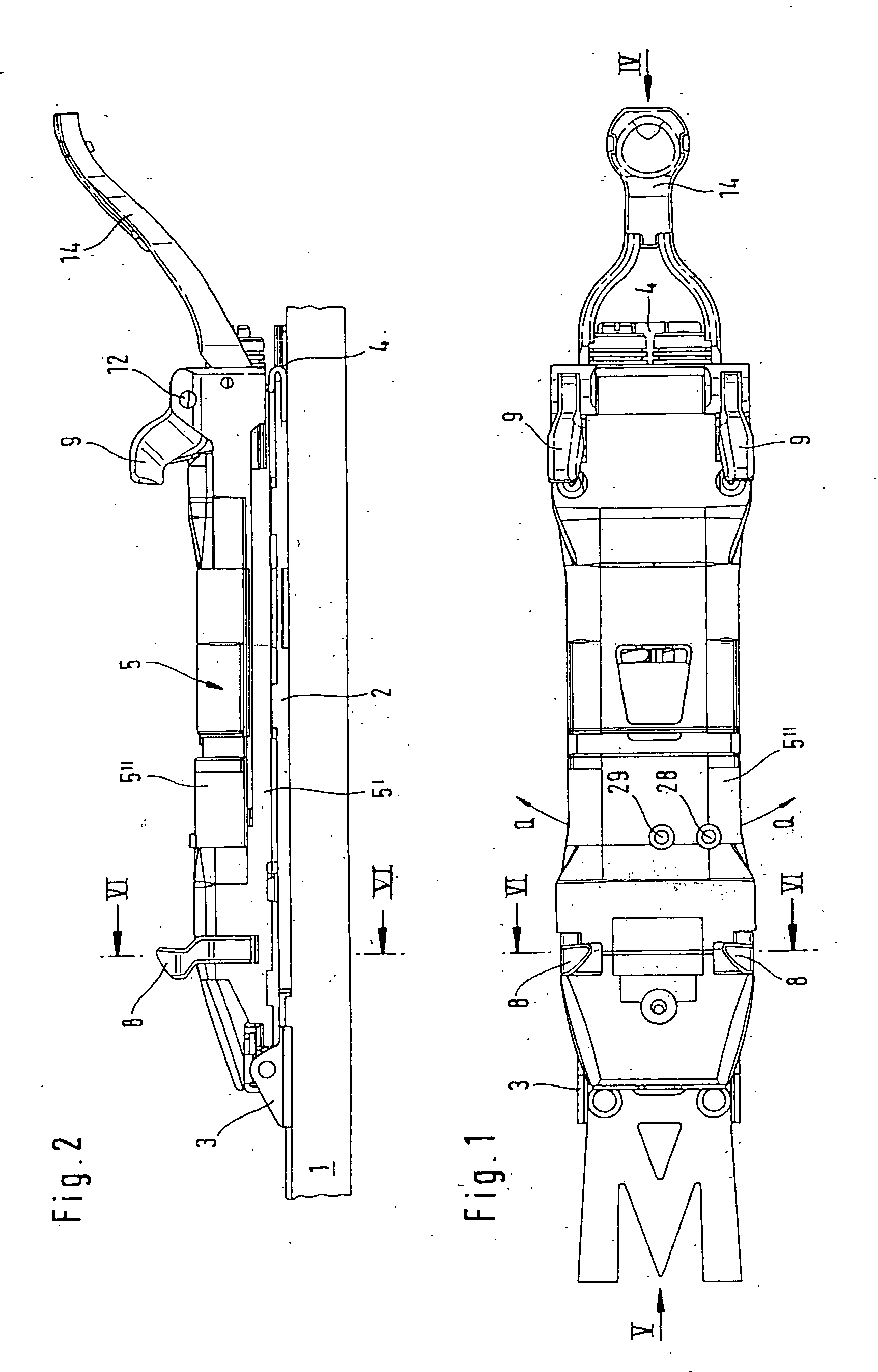
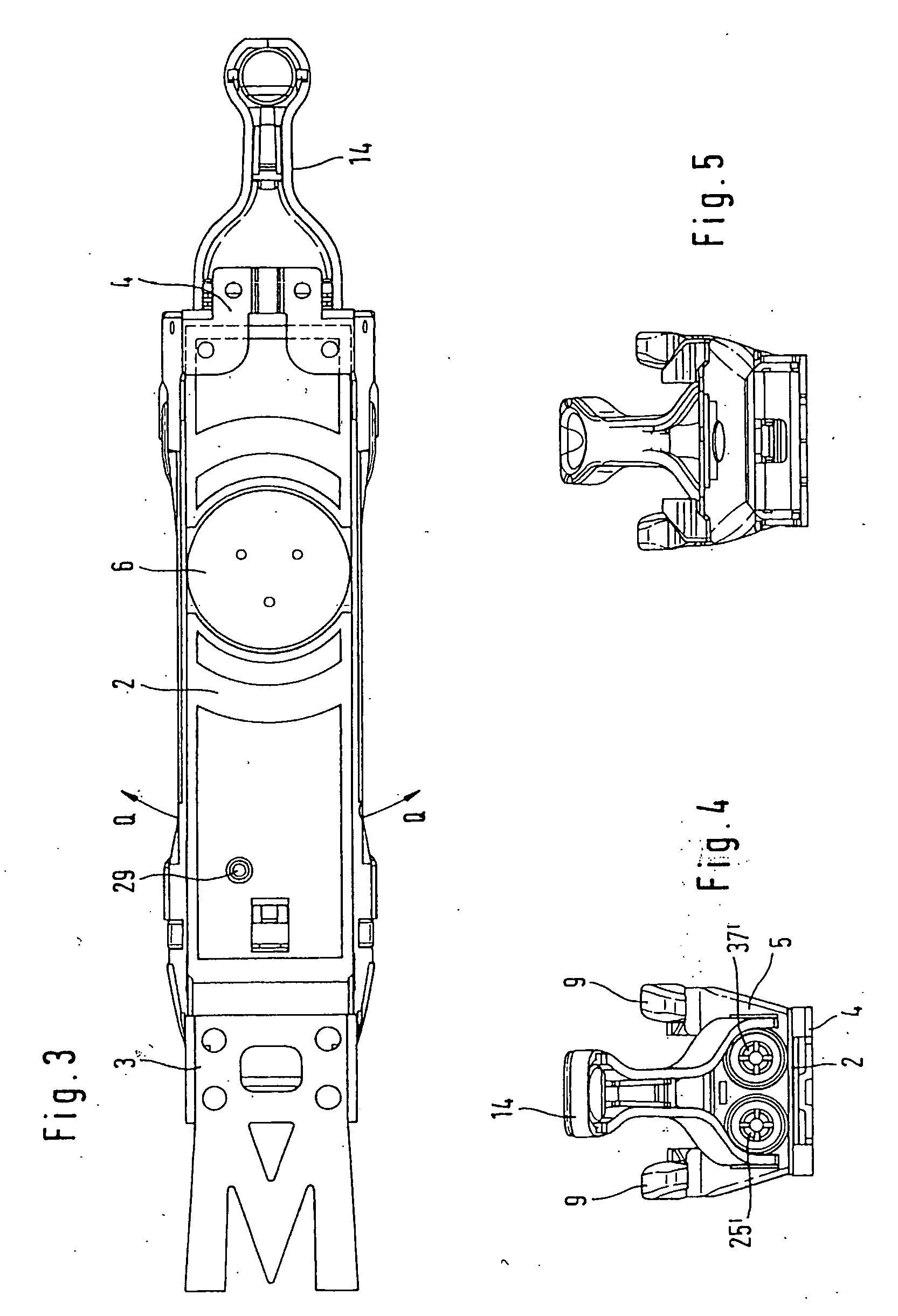
[0030] The binding according to the invention has a base plate 2 which is arranged on a ski 1, indicated partly in FIG. 2, which is connected at its front end, as seen in the longitudinal direction of the ski, in a hinge-like manner to a bearing part 3, arranged firmly on the ski, such that it can be pivoted about a transverse ski axis, and which is secured vertically, with displaceability in the longitudinal direction of the ski, at its rear end, as seen in the longitudinal direction of the ski, in a further ski-mounted bearing part 4.

[0031] Arranged on the base plate 2 is a standing and / or carrying plate 5, which can be rotated about a vertical axis of the base plate 2 and of which the top side serves as a standing and / or supporting surface for the sole of a ski boot which is to be inserted into the ski binding. The standing and / or carrying plate 5 has a bottom plate part 5′, designed as a frame and structural part, and a covering part 5″ on the top side. The abovementioned conne...


PUM


Abstract

A ski boot sole for cooperating with a ski binding to releasably hold the sole in the binding, the sole having front and rear recesses with front and rear fitting plates. The front recess and the front fitting plate are engaged by the front sole holder rotatable about a longitudinal axis for releasably holding the front sole holder against displacement in the forward, sideways and vertical directions. The rear recess and rear fitting plate are engageable by the rear sole holder which is rotatable about a transverse axis. The rear sole holder butts against the portion of the fitting plate extending outside the border of the sole to secure the rear portion of the sole in the rearward, sideways and vertical directions.

Description

CROSS REFERENCE TO RELATED APPLICATION [0001] This application is a continuation of U.S. patent application Ser. No. 10 / 723,336 filed Nov. 26, 2003, which claims priority from German patent application Serial No. 102 55 499.4 filed Nov. 27, 2002.BACKGROUND OF THE INVENTION [0002] 1. Field of the Invention [0003] The invention relates to a ski boot soles and to the combination of ski boot soles and ski boot bindings. [0004] 2. Description of the Prior Art [0005] In the case of virtually all ski bindings which are currently available on the market, a front boot-retaining unit and a rear boot-retaining unit are arranged on the ski, the front boot-retaining unit interacting in a formfitting manner with the toe end, and the rear boot-retaining unit interacting in a formfitting manner with the heel end, of the “standard” sole of a ski boot. To be precise, the front boot-retaining unit prevents the toe end of the sole from moving forward in the longitudinal direction of the ski and from mo...

Claims


Application Information

Patent Timeline
Patent Type & Authority Applications(United States)
IPC IPC(8): A63C9/00A63C9/08A63C9/084A63C9/085A63C9/086
CPCA63C9/0805A63C9/0807A63C9/0842A63C9/086A63C9/08528A63C9/08564A63C9/0847
Inventor KRUMBECK, MARKUSMANGOLD, MICHAELMANN, ANDREASMAREGA, ANTONELLOGABRIELLI, ANDREA
Owner MARKER DEUTLAND
Learn More