Control device for automatic transmission

a control device and automatic transmission technology, applied in the direction of gearing control, gearing element, belt/chain/gearing, etc., can solve the problems of torsional vibration in the rotary shaft, increased meshing force of the gear pair, and inability to perform the shift disengagement, etc., to achieve rapid shift transmission and suppress vibration

Active Publication Date: 2014-01-09
SUZUKI MOTOR CORP
View PDF4 Cites 2 Cited by
  • Summary
  • Abstract
  • Description
  • Claims
  • Application Information

AI Technical Summary

Benefits of technology

[0014]That is, when the shift transmission request is detected, the low load is applied in the preload control to thus release a little the coupling state of the gear pairs and the rotary shaft by the synchromesh mechanism, thereby reducing torsional load that would be applied to the rotary shaft of the automatic transmission. After that, the predetermined time has elapsed and the torsional load has been reduced upon the execution of the shift control. Therefore, it is possible to reduce the vibrations occurring when the coupling of the gear pairs and the rotary shaft is released by the synchromesh mechanism. Also, the preload is applied, so that the time necessary to reach a target load for performing the shift control is shortened. Thereby, it is possible to shorten the time necessary for the shift change.

Problems solved by technology

If a shift disengagement operation for switching the gear pairs of the transmission starts immediately at the time of releasing the automatic clutch upon shift transmission control, a torsional vibration occurs in the rotary shafts due to the automatic clutch being released.
Thus, the meshing force of the gear pairs is increased, so that it is not possible to perform the shift disengagement.
According to Patent Document 1, however, since the starting time of the shift disengagement is determined based on the timing at which the torque at the input shaft-side and the torque at the output shaft-side are balanced, the balance time of the torques may be late.
Thereby, even in a driving situation where the acceleration or deceleration is necessary, the shift transmission is not rapidly made, so that the mileage or operability may be deteriorated.
As a result, even in the driving situation where the acceleration or deceleration is necessary, the shift transmission is not rapidly made, so that the mileage or operability may be deteriorated.

Method used


Image

  • Control device for automatic transmission
  • Control device for automatic transmission
  • Control device for automatic transmission

Examples


Embodiment Construction

[0031]Reference will now be made in detail to the present embodiments of the present invention, examples of which are illustrated in the accompanying drawings, wherein like reference numerals refer to the like elements throughout. The embodiments are described below in order to explain the present invention by referring to the figures.

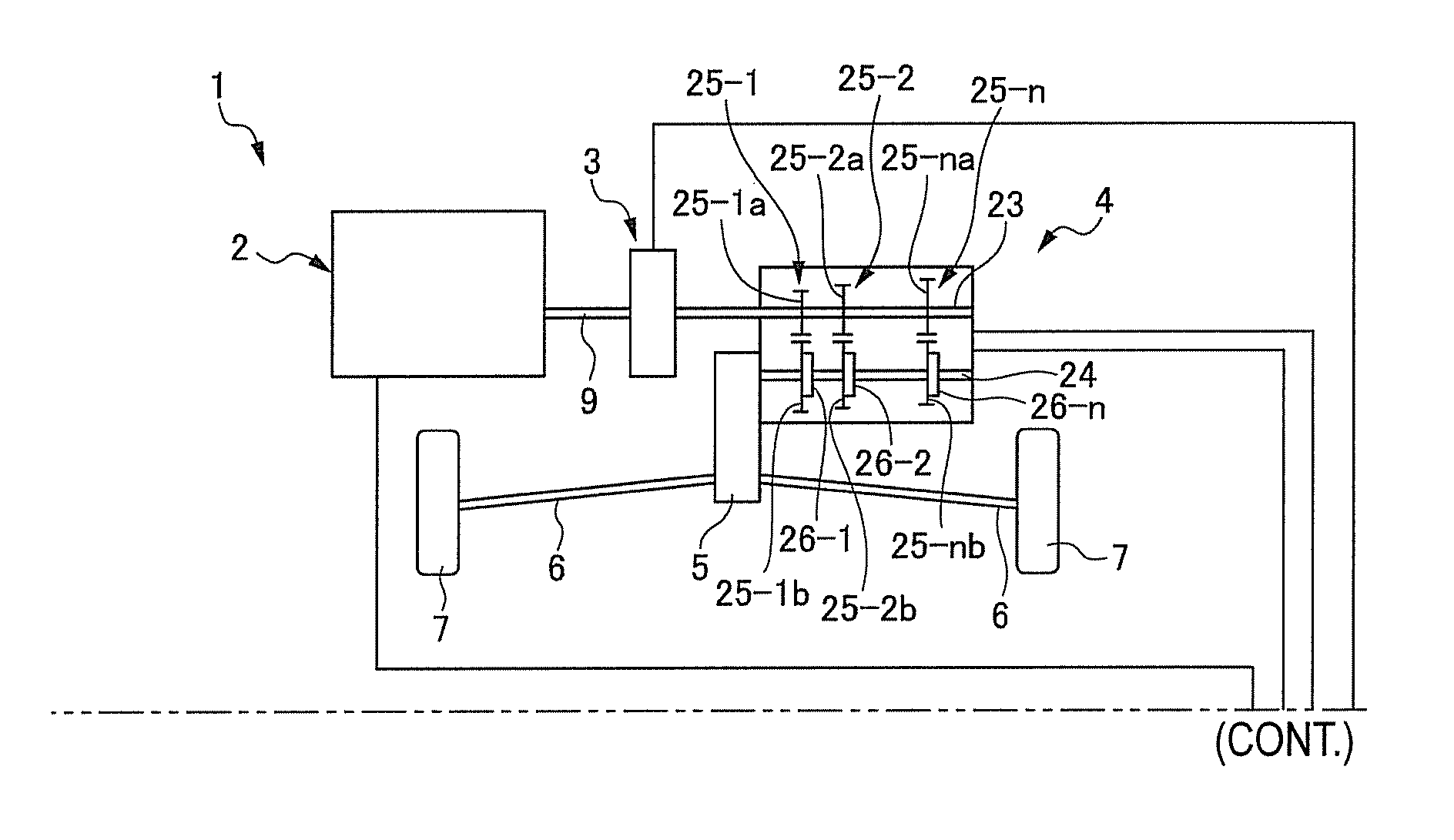
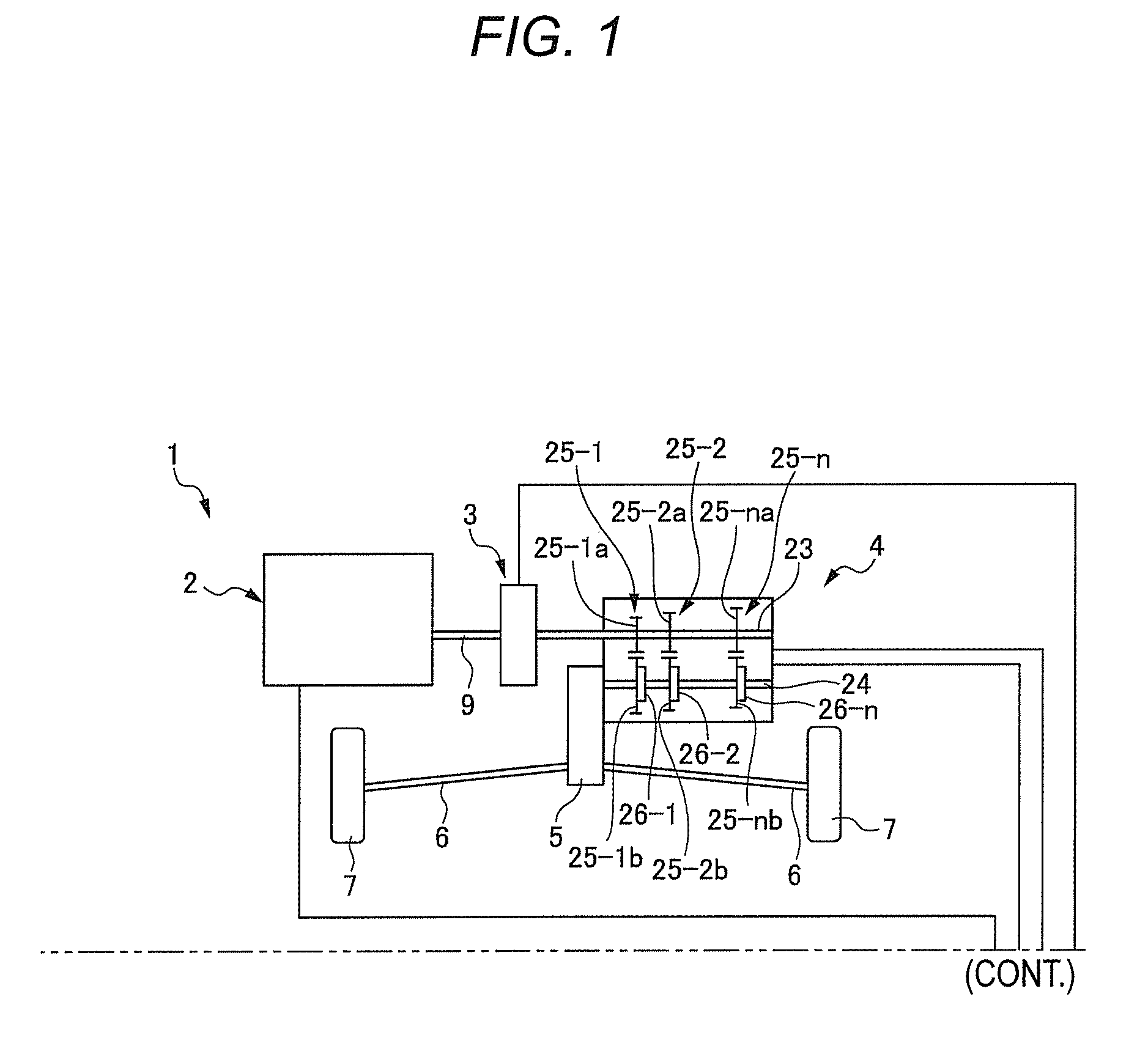
[0032]FIGS. 1 to 13 show an embodiment of the invention. In FIG. 1, a reference numeral ‘1’ indicates a vehicle, a reference numeral ‘2’ indicates an engine that is a motor, a reference numeral ‘3’ indicates an automatic clutch that transmits and interrupts a driving force and a reference numeral ‘4’ indicates an automatic transmission that converts the driving force. The driving force that is generated by the engine 2 is input to the automatic transmission 4 through the automatic clutch 3 and is converted by the automatic transmission 4, which is then transmitted to driving axles 6 by a differential member 5 and drives driving wheels 7 to thus run the...


PUM


Abstract

There is provided a control device for an automatic transmission configured to automatically shift a transmission of a driving force of a motor in response to a driving state. The automatic transmission includes a synchromesh mechanism configured to couple gear pairs and a rotary shaft to transmit the driving force of the motor to the gear pairs and a switching apparatus configured to switch a coupling state of the gear pairs and the rotary shaft. A preload control unit is configured to operate the switching apparatus to apply a preload to the synchromesh mechanism when a shift transmission request is detected. A shift control unit is configured to operate the switching apparatus to apply a shift load greater than the preload to the synchromesh mechanism after the preload is applied to the synchromesh mechanism.

Description

CROSS-REFERENCE TO RELATED APPLICATIONS[0001]The disclosure of Japanese Patent Application No. 2012-153249 filed on Jul. 9, 2012, including specification, drawings and claims is incorporated herein by reference in its entirety.BACKGROUND OF THE INVENTION[0002]1. Field of the Invention[0003]The invention relates to a control device for an automatic transmission, and more particularly, to a control device for an automatic transmission capable of performing a process from a shift transmission starting to a shift transmission completion in a short time.[0004]2. Description of the Related Art[0005]An automatic transmission is provided with a plurality of gear pairs (input shaft-side gear and output shaft-side gear) of a constant mesh type between a rotary shaft of an input-side and a rotary shaft of an output-side, a synchromesh mechanism for switching the gear pairs between a power transmission state and a power non-transmission state by using an actuator, and a switching apparatus for ...

Claims


Application Information

Patent Timeline
Patent Type & Authority Applications(United States)
IPC IPC(8): F16H61/68
CPCF16H61/68F16H59/14F16H61/08F16H61/682F16H2059/147F16H2061/2823F16H61/2807F16H61/0437F16H2061/0474F16H2059/6807
Inventor SUZUKI, KAZUHIKOYAGI, SHOJI
Owner SUZUKI MOTOR CORP
Why Eureka
Try Eureka