
Monitoring humidity measurement system and monitoring humidity measurement method

a humidity measurement and humidity measurement technology, applied in the direction of heat measurement, instruments, converting sensor output optically, etc., can solve the problems of difficult large-scale installation on a farm, short measurement device to sensor, unsuitable for recognizing a range of several tens of km in a distributed manner, etc., to shorten the time taken for frequency shift change measurement, the effect of humidity measuremen

Active Publication Date: 2022-03-22
NEUBREX
View PDF5 Cites 0 Cited by
  • Summary
  • Abstract
  • Description
  • Claims
  • Application Information

AI Technical Summary

Benefits of technology

The present disclosure aims to provide a device and method for measuring humidity using an optical fiber, without being influenced by temperature change, and shortening the time required for frequency shift changes in measurement. This enables real-time and distributed measurement of humidity across a land area. The invention is made through an optical cable that enables the monitoring of environmental variables. Overall, the technical effects of the invention revolve around improving the accuracy and reliability of humidity measurements in environmental monitoring.

Problems solved by technology

However, there are a lot of problems, e.g., the distance from a measurement device to a sensor is short, a power supply is needed, and heat generation in an electric wire influences environmental variables.
Therefore, it is difficult to perform large-scale installation on a farm.
These methods are methods for one-point or multiple-point measurement, and therefore are unsuitable for recognizing a range of several tens of km in a distributed manner.
Thus, there is a problem that it is difficult to perform real-time measurement within a time of about thirty minutes and this method is unsuitable for distributed measurement.
Thus, there is a problem that it is difficult to make separation from the amount of temperature change which causes an influence at the same time.

Method used


Image

  • Monitoring humidity measurement system and monitoring humidity measurement method
  • Monitoring humidity measurement system and monitoring humidity measurement method
  • Monitoring humidity measurement system and monitoring humidity measurement method

Examples


first embodiment

[0031][Conceptual Model]

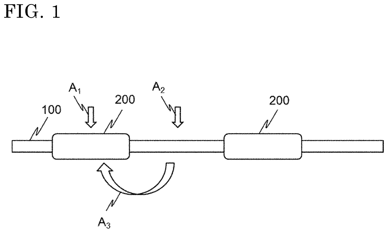
[0032]First, an optical fiber used for a monitoring humidity measurement system according to the first embodiment will be described below, with reference to a conceptual model shown in FIG. 1. In order to measure agricultural data (humidity, nutrient, and the like), “temperature” or “strain” which can be measured by an optical fiber needs to be associated with the agricultural data. Normally, in measurement using an optical fiber, frequency shifts due to “temperature” and “strain” occur at the same time in an optical fiber, and therefore it is necessary to separate influences of these (see, for example, Patent Document 2). Meanwhile, it is shown that humidity which is one of agricultural data can be measured by an optical fiber as described in the above Background Art.

[0033]Accordingly, in the first embodiment, on the premise that humidity which is one of the agricultural data is to be measured in a distributed manner, the following is considered: a water-abs...


PUM

PropertyMeasurementUnit
Wavelengthsaaaaaaaaaa
thicknessaaaaaaaaaa

Abstract

A monitoring humidity measurement system includes: a humidity measurement optical fiber including a first optical fiber and a humidity detection layer provided so as to annularly cover the first optical fiber; a reference optical fiber including a second optical fiber; a plurality of optical communication cables; and a signal processing device configured to, with a laser beam entering into the first and second optical fibers, calculate and obtain Brillouin frequency shift and Rayleigh frequency shift of backscatter light from the first and second optical fibers based on the entering laser beam, and store predetermined constants, wherein reference data and target data are measured from the Rayleigh frequency shift and an initial humidity value calculated from the Brillouin frequency shift, and the value of humidity at the present time is calculated on the basis of Rayleigh frequency shift per unit humidity calculated from a difference between the above two data.

Description

BACKGROUND OF THE INVENTION1. Field of the Invention[0001]The present disclosure relates to a monitoring humidity measurement system and a monitoring humidity measurement method.2. Description of the Background Art[0002]Conventionally, environmental variables in soil of a farm field, an orchard, or the like, e.g., temperature, humidity, nitrogen concentration, phosphorus concentration, and potassium concentration, have been important indices in cultivation of crops. In addition, in a national guideline, promotion of precision agriculture is required, so that means for measuring data over a range of several tens of km in a distributed manner and in real time is needed. In consideration of needs in agriculture, the above technical means is required to have the following properties: a prolonged life of about ten years, a comparatively easy installation manner, a sufficient mechanical strength, flexibility for also adapting to farm machine work, ease of repair for damage, capability of ...

Claims


Application Information

Patent Timeline
Patent Type & Authority Patents(United States)
IPC IPC(8): G01D5/353G01K11/32G01K11/322
CPCG01D5/35358G01D5/35303G01K11/32G01K11/322G01D5/35361G01D5/35364
Inventor NAKAMICHI, MASANORINAKAO, KAZUSHIGEKISHIDA, KINZO
Owner NEUBREX
Learn More