Clutch control device

a technology of clutch engagement and control device, which is applied in the direction of fluid actuated clutches, non-mechanical actuated clutches, clutches, etc., can solve the problems that the time required for changing the clutch engagement state cannot be compatibly achieved, and the vehicle cannot be suffocated during the clutch engagement. it can achieve the effect of shortening the time required and suppressing the vibration generated in

Active Publication Date: 2020-08-18
NIDEC TOSOK CORP
View PDF11 Cites 0 Cited by
  • Summary
  • Abstract
  • Description
  • Claims
  • Application Information

AI Technical Summary

Benefits of technology

[0004]The present invention is made in view of the above-described circumstances, and an object thereof is to provide a clutch control device which can compatibly achieve suppressing vibration generated in a vehicle and shortening a time required for changing a clutch engagement state.
[0006]According to the aspect of the present invention, there is provided a clutch control device which can compatibly achieve suppressing vibration generated in a vehicle and shortening a time required for changing a clutch engagement state.

Problems solved by technology

In addition, according to the clutch control device in the related art as described above, if the time required for changing the clutch engagement state needs to be shortened, the vibration generated in the vehicle during the clutch engagement cannot be suppressed in some cases.
That is, according to the clutch control device in the related art as described above, there is a problem in that suppressing the vibration generated in the vehicle and shortening the time required for changing the clutch engagement state cannot be compatibly achieved.

Method used


Image

  • Clutch control device
  • Clutch control device
  • Clutch control device

Examples


Embodiment Construction

[0011]Hereinafter, a clutch control device according to an embodiment of the present invention will be described with reference to the drawings. A scope of the present invention is not limited to the following embodiment, and can be optionally modified within a technical idea of the present invention.

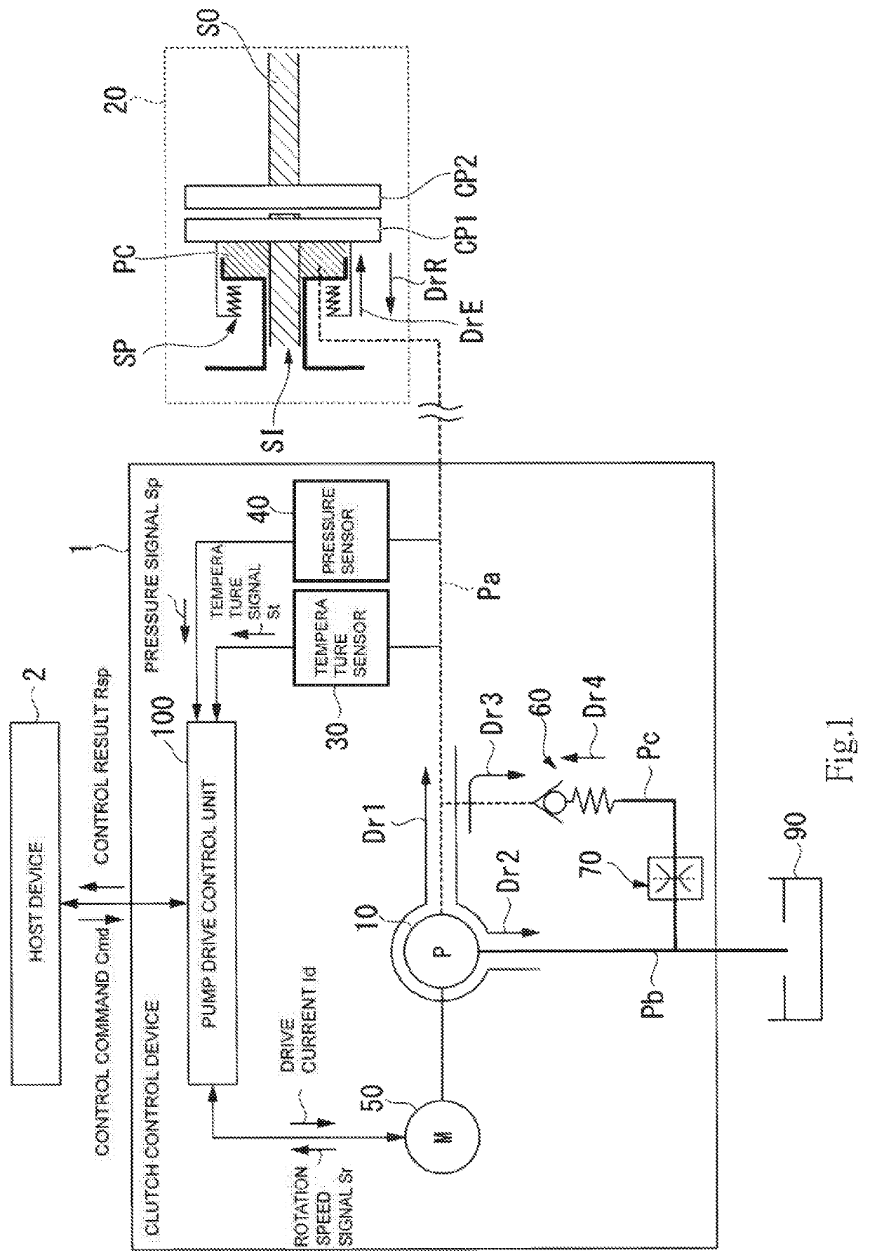
[0012]Referring to FIG. 1, a clutch control device 1 according to the present embodiment will be described. FIG. 1 is a block diagram illustrating an example of a configuration of the clutch control device 1 according to the embodiment. The clutch control device 1 supplies hydraulic pressure to a clutch unit 20 of a vehicle, based on a control command Cmd issued by a host device 2.

[0013]The clutch unit 20 includes an input shaft SI, an input-side clutch plate CP1, an output shaft SO, an output-side clutch plate CP2, a piston chamber PC, and a release spring SP. A rotational force output from a motor (not illustrated) is transmitted to the input shaft SI. Hydraulic oil is supplied to the...


PUM


Abstract

There is provided a clutch control device which includes an electric oil pump, a clutch unit, and a pressure measurement unit, and which controls an operation of the electric oil pump so as to change a transmission state of the clutch unit. The device includes a pressure control valve that is located between an oil passage for connecting the electric oil pump and the clutch unit to each other and an oil pan for storing an unpressurized hydraulic oil, and that discharges the pressurized hydraulic oil from the oil passage to the oil pan, when pressure of the hydraulic oil exceeds valve opening pressure, and a pump drive control unit that controls hydraulic pressure by driving the electric oil pump, based on target pressure indicated by a change command of the transmission state of the clutch unit and the hydraulic pressure measured by the pressure measurement unit.

Description

BACKGROUND OF THE INVENTION1. Field of the Invention[0001]The present invention relates to a clutch control device.2. Description of the Related Art[0002]For example, an in-vehicle clutch control device has been proposed which controls a clutch engagement state by causing an electric oil pump to change hydraulic pressure of a piston chamber of a clutch. For example, Pamphlet of International Publication No. 2012 / 141128 is known.[0003]According to the clutch control device in the related art as described above, if vibration generated in a vehicle during clutch engagement needs to be suppressed, a time required for changing a clutch engagement state is prolonged in some cases. In addition, according to the clutch control device in the related art as described above, if the time required for changing the clutch engagement state needs to be shortened, the vibration generated in the vehicle during the clutch engagement cannot be suppressed in some cases. That is, according to the clutch ...

Claims


Application Information

Patent Timeline
Patent Type & Authority Patents(United States)
IPC IPC(8): F16D48/02F16D48/06
CPCF16D48/02F16D48/066F16D25/14F16D2500/3024F16D2300/18F16D2500/70448F16D2500/3042F16D2500/1024F16D2048/0233F16D2500/1026F16D2500/3067F16D2500/70406F16D2500/50293F16D2048/0245F16D2048/0221
Inventor ETO, TAKAMITSUSAGARA, FUMIYA
Owner NIDEC TOSOK CORP
Why Eureka
Try Eureka