Particle beam therapy system

a beam therapy and particle technology, applied in the field of particle beam therapy system, can solve the problems of prolonging the time required to change energy levels, and extending the therapeutic irradiation time. , to achieve the effect of improving dose rates, shortening the time required, and increasing beam utilization efficiency

Active Publication Date: 2017-10-03
HITACHI LTD
View PDF11 Cites 0 Cited by
  • Summary
  • Abstract
  • Description
  • Claims
  • Application Information

AI Technical Summary

Benefits of technology

[0010]It is therefore an object of the present invention to provide a particle beam therapy system using a synchrotron that extracts a charged particle beam at a plurality of energy levels during an extraction phase by successively accelerating or decelerating an orbiting beam during that phase to change the beam energy, the system being arranged to shorten the time required for the energy change in order to improve dose rates and shorten therapeutic irradiation time with the scanning method. Another object of the present invention is to provide a particle beam therapy system that keeps the synchrotron from getting larger in size and higher in cost.
[0013]Preferably, upon acceleration or deceleration of the charged particle beam during the extraction phase of the synchrotron, the synchrotron may suppress the extraction of the unnecessary charged particle beam by having an acceleration frequency controlled to enlarge the stability limit in size.
[0015]According to this invention, it is possible to improve dose rates by shortening the time required to change energy levels during the extraction phase and by raising the efficiency in beam utilization while keeping the system from getting larger in size and higher in cost, whereby therapeutic irradiation time with the scanning method can be shortened.

Problems solved by technology

This poses the problem about prolonged therapeutic irradiation time because of reduced dose rates.
However, the disclosed method is not necessarily sufficient to attain the required standard nominal value of 2 Gy / min in dose rate for every 1 L of irradiation volume.
This method entails the problem about low speed response of the quadrupole electromagnet because of their large inductance values, which prolongs the time required to change energy levels.
Although there exists a method involving a synchrotron being separately equipped with dedicated small-inductance quadrupole electromagnet permitting high-speed response, this method can lead to the synchrotron getting larger in size and higher in cost.
This is not a realistic option for the synchrotron for proton-beam treatment that must be small in size and low in cost.

Method used


Image

  • Particle beam therapy system
  • Particle beam therapy system
  • Particle beam therapy system

Examples


first embodiment

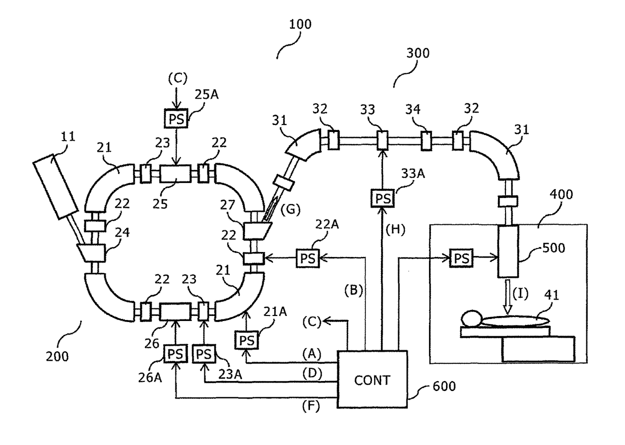
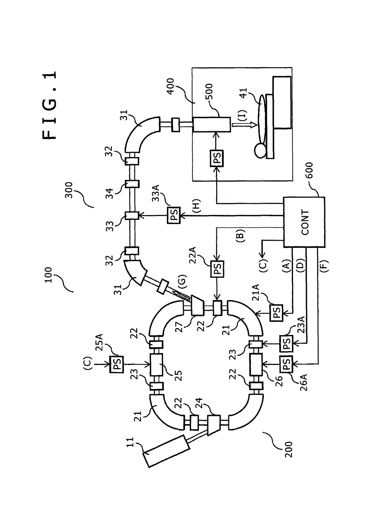
[0025]The configuration and the operation of a particle beam therapy system 100 practiced as the first embodiment of the present invention are explained below with reference to FIGS. 1 through 4H. Explained first with reference to FIG. 1 is an overall configuration of the particle beam therapy system 100 as the first embodiment.

[0026]The particle beam therapy system 100 includes a synchrotron 200 that accelerates to a predetermined energy level a charged particle beam pre-accelerated by a pre-accelerator 11 such as a linac before extracting the accelerated charged particle beam, a beam transportation system 300 that transports the charged particle beam extracted from the synchrotron 200 up to a treatment room 400, an irradiation device 500 that irradiates a patient 41 in the treatment room 400 with the charged particle beam in conformity to the patient's tumor shape, and a control apparatus 600.

[0027]The control apparatus 600 controls the devices constituting the pre-accelerator 11,...

second embodiment

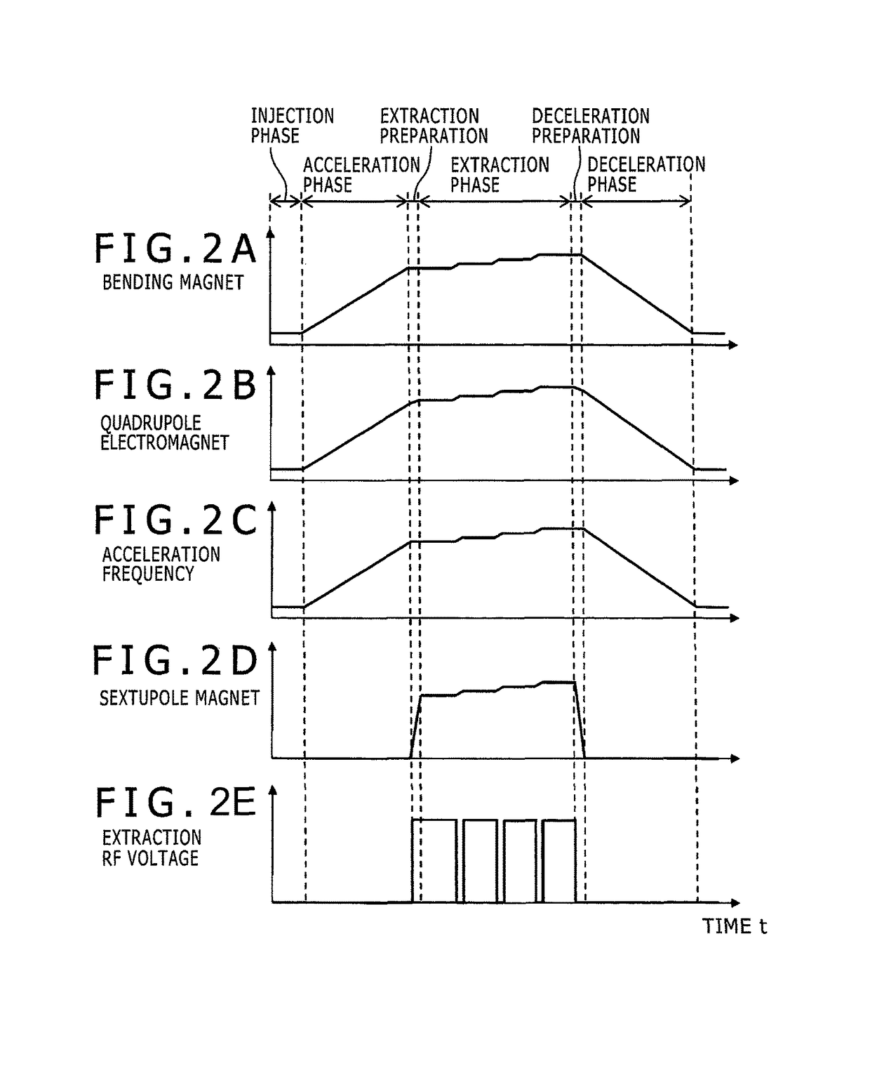
[0048]The configuration and the operation of a particle beam therapy system as the second embodiment of the present invention are now explained. The overall configuration of the particle beam therapy system as the second embodiment is the same as that of the first embodiment in FIG. 1. The operation sequence of the synchrotron is the same as that of the first embodiment in FIGS. 2A through 2E except for during the extraction phase. Also, the structure and the operating principle of the irradiation device are the same as those of the first embodiment in FIGS. 3A and 3B. Explained below are some differences in the operation sequence during the extraction phase of the synchrotron between the first embodiment and the second embodiment.

[0049]In FIGS. 4A through 4H showing a detailed operation sequence and time changes in operation parameters during the extraction phase of the synchrotron, broken lines correspond to the second embodiment and are indicative of the differences from the firs...

third embodiment

[0053]The configuration and the operation of a particle beam therapy system as the third embodiment of the present invention are now explained. An overall configuration of the particle beam therapy system as the third embodiment is shown in FIG. 5, and a detailed operation sequence and time changes in operation parameters during the extraction phase of the synchrotron are depicted in FIGS. 6A through 6G. Below is an explanation of only the differences between the third embodiment on the one hand and the first and the second embodiments on the other hand.

[0054]As with the second embodiment, the third embodiment involves controlling the frequency of the rf voltage (acceleration frequency) applied to the accelerating cavity in the energy changing segments so as to enlarge the size of the stability limit (size of the stable area), as shown in FIGS. 6C and 6D. This makes it possible to fully suppress the current of the extracted beam from the synchrotron in the energy changing segments a...


PUM


Abstract

A particle beam therapy system is disclosed which includes: a synchrotron accelerating a charged particle beam injected from a pre-accelerator up to a predetermined energy level before applying a high-frequency voltage to an extraction device to extract the charged particle beam caused to exceed a stability limit; a beam transportation system transporting the charged particle beam extracted from the synchrotron up to a treatment room, and an irradiation device irradiating a patient in the treatment room with the charged particle beam in conformity to the patient's tumor shape. The synchrotron has functionality to accelerate or decelerate the charged particle beam successively to extract the charged particle beam at a plurality of energy levels during an extraction phase of the synchrotron, the beam transportation system further having functionality to block off an unnecessary charged particle beam extracted from the synchrotron during acceleration or deceleration.

Description

BACKGROUND OF THE INVENTION[0001]1. Field of the Invention[0002]The present invention relates to a particle beam therapy system capable of highly accurate therapeutic irradiation. More particularly, the invention relates to a particle beam therapy system that uses advanced irradiation technology such as the scanning method capable of highly precise therapeutic irradiation in conformity to a complex target shape.[0003]2. Description of the Related Art[0004]Against the background of an aging society in recent years, attention has been drawn to radiation therapies which, as cancer treatment, are minimally invasive to the body and permit a high quality of life to be maintained after the treatment. One of the most promising of these therapies is the particle beam therapy system that offers good dose concentration on the tumor using a charged particle beam of protons, carbon particles, etc., accelerated by an accelerator. The particle beam therapy system is typically composed of an accele...

Claims


Application Information

Patent Timeline
Patent Type & Authority Patents(United States)
IPC IPC(8): H05H13/04H05H7/10A61N5/10H05H7/00
CPCA61N5/1077H05H7/10H05H13/04A61N2005/1087H05H2007/004
Inventor SAITO, KAZUYOSHINOMURA, TAKUYANISHIUCHI, HIDEAKI
Owner HITACHI LTD
Why Eureka
Try Eureka