Image forming apparatus

US20070036580A1Active Publication Date: 2007-02-15HEWLETT PACKARD DEV CO LP

Image

  • Image forming apparatus
  • Image forming apparatus
  • Image forming apparatus

Examples


Embodiment Construction

[0032] Reference will now be made in detail to embodiments of the invention, examples of which are illustrated in the accompanying drawings, wherein like reference numerals refer to the like elements throughout. The embodiments are described below in order to explain aspects of the invention by referring to the figures, with well-known functions or constructions not necessarily being described in detail.

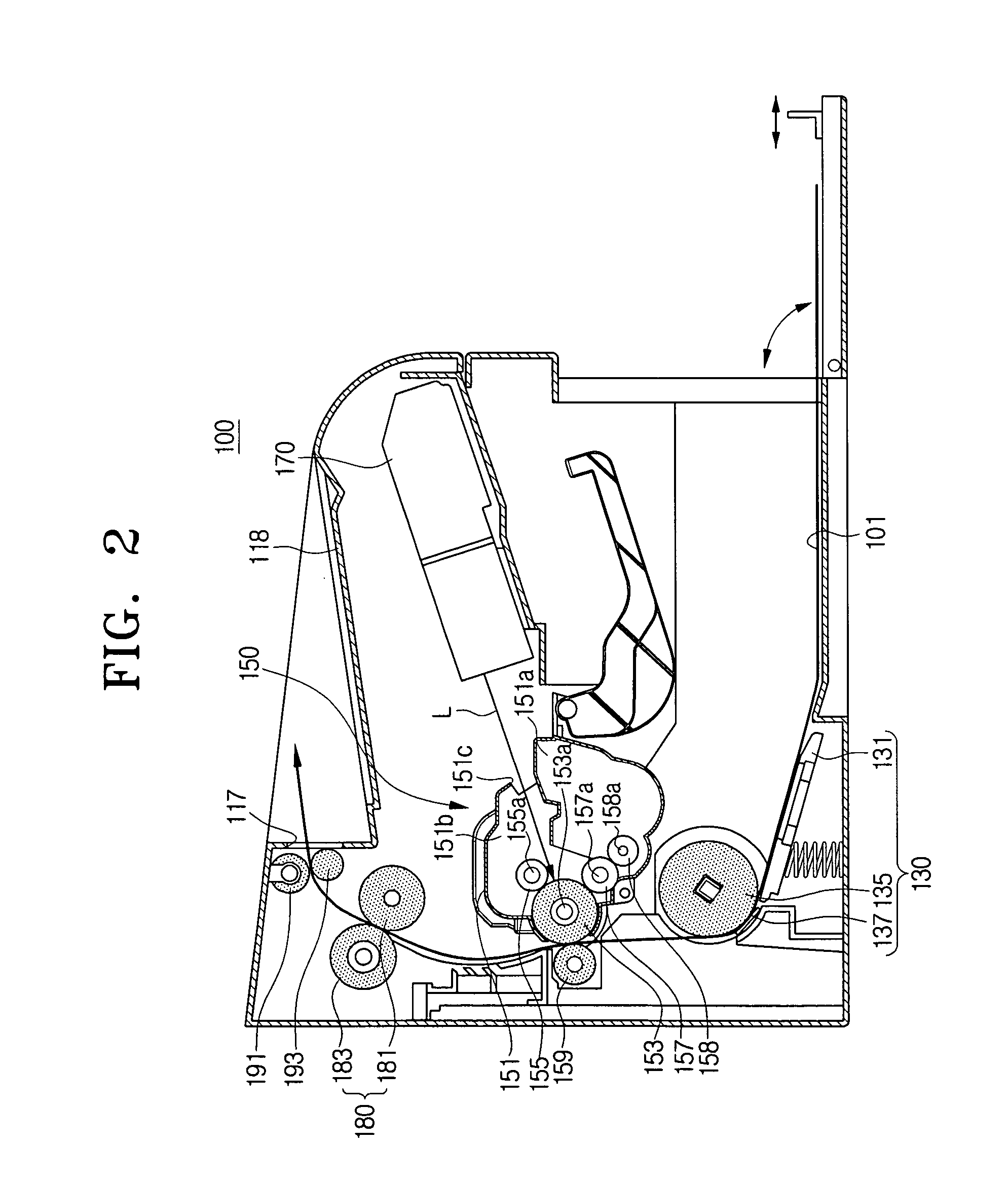
[0033]FIG. 2 is a functional diagram illustrating an overall operation of an image forming apparatus 100 according to an embodiment of the invention. Referring to FIG. 2, when a pick-up roller 135 rotates in response to a print command, through a frictional force between the pick-up roller 135 and a friction pad 137, a sheet of recording media 101 is separated from the recording media 101 loaded on the upper surface of a knock-up plate 131 and then fed between a photosensitive drum 153 and transferring roller 159. According to aspects of the invention the image forming apparatus 100...


PUM


Abstract

An image forming apparatus includes: a main frame; a developing unit, the developing unit including a photosensitive drum to form an electrostatic latent image on an outer surface thereof, a developing roller installed at one side of the photosensitive drum to develop the formed electrostatic latent image, and a developer plate having a drum shaft support groove to support both ends of a photosensitive drum shaft supporting the photosensitive drum and a roller shaft support groove to support both ends of a developing roller shaft supporting the developing roller; and a gap regulating mechanism to vary a gap between the photosensitive drum and developing roller in response to attachment / detachment of the developing unit to / from the main frame. Such image forming apparatus can promote preventing a migration phenomenon that low molecular weight elements leak out from particles constituting the developing roller or photosensitive drum, or that the rollers are squeezed.

Description

CROSS-REFERENCE TO RELATED APPLICATIONS [0001] This application claims benefit under 35 U.S.C. §119(a) of Korean Patent Application No. 2005-74505, filed Aug. 12, 2005 in the Korean Intellectual Property Office, the entire contents of which are incorporated herein by reference. BACKGROUND OF THE INVENTION [0002] 1. Field of the Invention [0003] Aspects of the invention relate to an image forming apparatus. More particularly, aspects of the invention relate to an image forming apparatus which permits adjustment of a gap between a photosensitive drum and a developing roller. [0004] 2. Description of the Related Art [0005] Generally, an electro-photographic image forming apparatus, such as a laser beam printer, produces a desired image by forming an electrostatic latent image on a photosensitive medium such as a photosensitive drum or photosensitive belt, developing the formed electrostatic latent image using developing materials having predetermined colors, and transferring the develo...

Claims


Application Information

Patent Timeline
15 Feb 2007
Publication
US20070036580A1
IPC
G03G21/18
CPC
G03G15/0813; G03G15/06; G03G15/0822; G03G2215/0634; G03G2215/0872
Inventors
NOH, JOO-HWAN