Electrical connector

Inactive Publication Date: 2010-12-14
DAIICHI SEIKO CO LTD
View PDF8 Cites 48 Cited by
  • Summary
  • Abstract
  • Description
  • Claims
  • Application Information

AI Technical Summary

Benefits of technology

[0033]With the electrical connector thus constituted in accordance with the present invention, as described above, it is not required, for causing the holding member formed in the conductive shell to be put in engagement with the flat circuit device inserted in the housing to hold the same and then to be released by the releasing member provided in the housing from the engagement with the flat circuit device to put the same in free, to provide on the housing an actuator rotatable in regard to the housing or to set the conductive shell to be rotatable in regard to the housing. Accordingly, the conductive shell fixed to the housing can be used for fastening the housing to the solid circuit board and any additional member for fastening the housing to the solid circuit board is not required. As a result, the electrical connector according to the present invention can be constituted with a relatively small number of constitutive parts and at a production cost reduced effectively.
[0034]In the electrical connector according to the present invention, since the holding member is automatically put in engagement with the flat circuit device to hold the same in the housing when the flat circuit device is inserted into the housing through the opening provided thereon and then the holding member is released from the engagement with the flat circuit device inserted in the housing when the second end portion of the releasing member, which projects from the inside to the outside of the conductive shell on the side of the first end surface of the housing opposite to the second end surface of the housing facing the solid circuit board, is pushed toward the inside of the conductive shell, the holding member can be released from the engagement with the flat circuit device inserted in the housing by extremely simple and easy operations and it is not necessary for carrying out such operations to provide an undesirable open space around the releasing member.
[0035]Further, since the conductive shell provided with the holding member formed therein is mounted on the housing to cover a major part of the same and connected electrically with the grounded portion provided on the solid circuit board, the conductive shell can be operative to contribute effectively to the adjustment on the characteristic impedance of each of the conductive contacts and to shield sufficiently the conductive contacts in the housing from electromagnetic wave noises from the

Problems solved by technology

In the case of the previously proposed electrical connector which has the holding means operative to shift its position in response to the rotational movements of the actuator provided to be rotatable in regard to the housing, the actuator provided to be rotatable in regard to the housing is required and this results in problems or disadvantages that the number of constitutive parts of the electrical connector increases undesirably and a production cost of the electrical connector rises disagreeably.
Further, it is necessary for causing the holding means to engage with or disengage from the flat circuit device inserted in the housing to rotate the actuator in regard to the housing and this results in undesirable increase in an open space around the electrical connector.
Besides, since the conductive shell is shaped to cover only an upper surface of the housing opposite to a lower surface of the same facing the main solid circuit board and side surfaces of the housing opposite each other in the direction along which the conductive contacts are arranged, a contribution by the conductive shell to the adjustment on characteristic impedance of each of the conductive contacts is inevitably reduced and a shielding effect by the conductive shell to the conductive contacts against the electromagnetic wave noises can not be obtained sufficiently.
Further, in the

Method used


Image

  • Electrical connector
  • Electrical connector
  • Electrical connector

Examples


Example

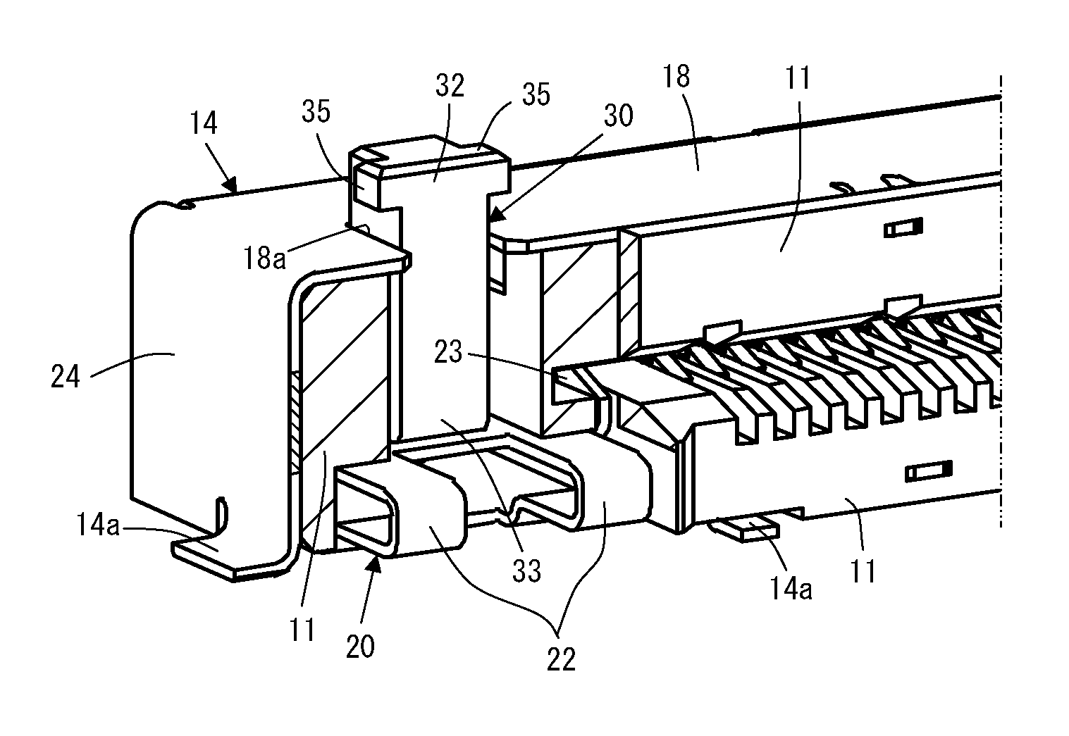
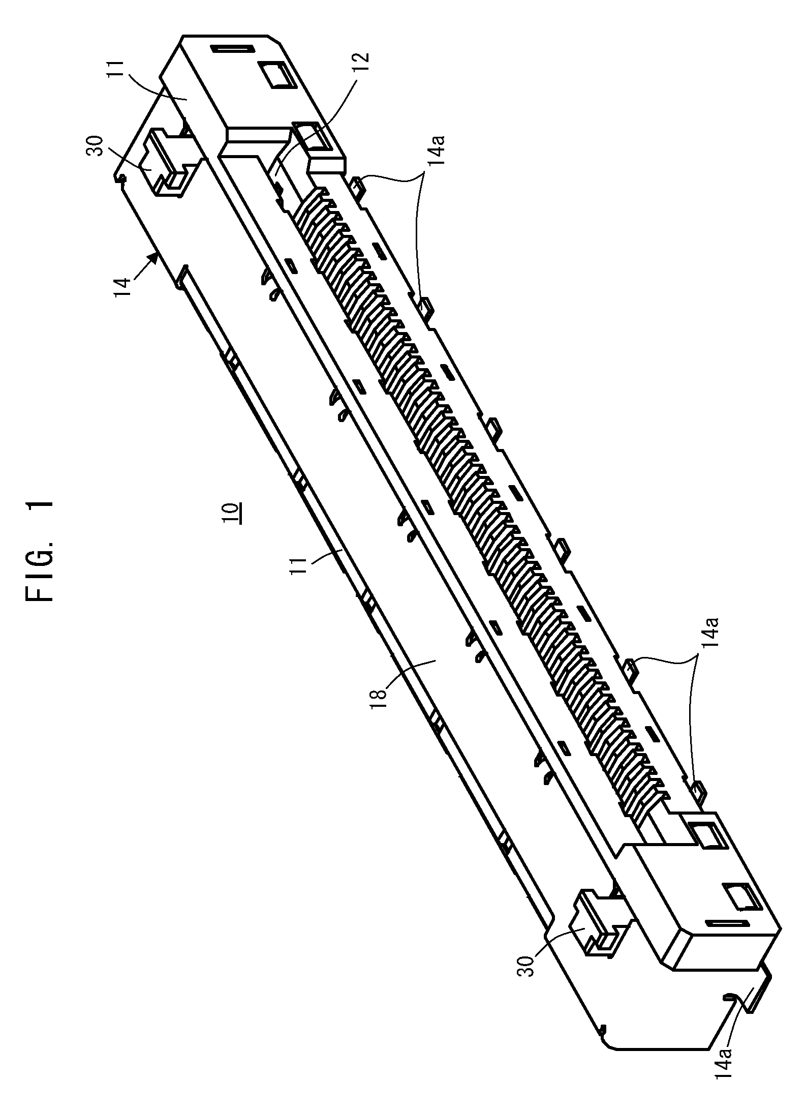
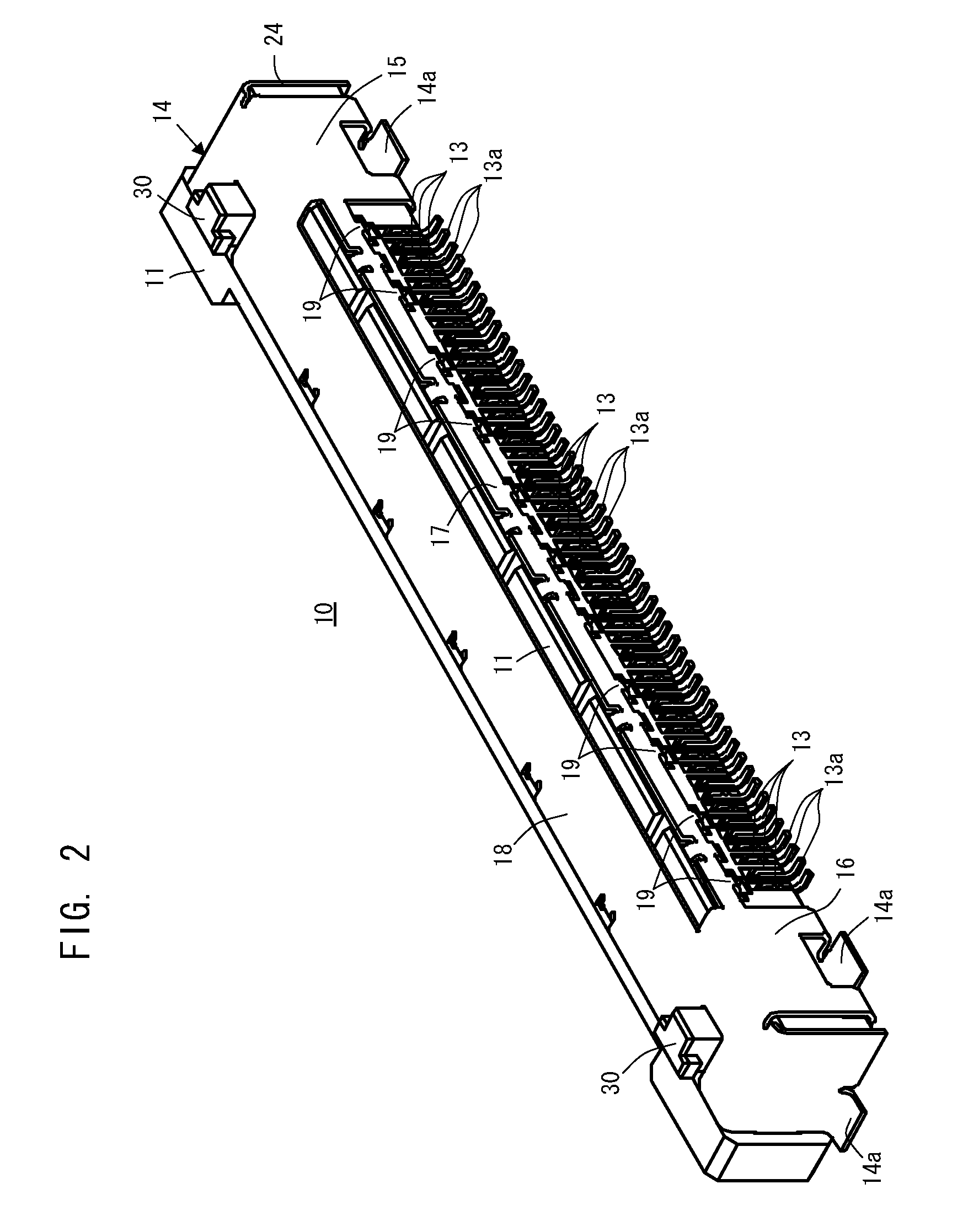
[0057]Each of FIG. 1 which is a schematic front, top and left side perspective view, FIG. 2 which is a schematic rear, top and left side perspective view and FIG. 3 which is a front view, shows an embodiment of electrical connector according to the present invention.

[0058]Referring to FIGS. 1 to 3, an electrical connector 10, which constitutes the embodiment of electrical connector according to the present invention, has a housing 11 made of insulator, such as plastics or the like. The housing 11 is provided in a front end portion thereof with an opening 12 through which a flat circuit device, such as an FPC, is inserted into the housing 11 and a room extending in the housing 11 from the opening 12 for accommodating the flat circuit device inserted in the housing 11.

[0059]When the electrical connector 10 is put in practical use for mounting, for example, an FPC constituting the flat circuit device on a solid circuit board in an electronic apparatus (not shown in the drawings), the h...


PUM


Abstract

An electrical connector including a housing provided with an opening through which a flat circuit device is inserted into the housing, a plurality of conductive contacts arranged on the housing, a conductive shell mounted on the housing for covering partially the same and provided with a holding member for engaging with the flat circuit device inserted in the housing to hold the same, and a releasing member formed in the housing with a first end portion thereof operative to be in contact with the holding member and a second end portion thereof operative to project from the inside to the outside of the conductive shell, wherein the releasing member is moved so that the first end portion thereof causes the holding member to be released from engagement with the flat circuit device inserted in the housing when the second end portion thereof is pushed toward the inside of the conductive shell under a condition wherein the holding member is put in the engagement with the flat circuit device inserted in the housing.

Description

BACKGROUND OF THE INVENTION[0001]1. Field of the Invention[0002]The present invention relates generally to an electrical connector, and more particularly to an improvement in an electrical connector which has a housing, a plurality of conductive contacts arranged in the housing for coming into press-contact with connecting terminals provided on a flat circuit device, such as a flexible printed circuit board (hereinafter, referred to as an FPC) or a flexible flat cable assembly (hereinafter, referred to as an FFC) inserted in the housing, so as to put the flat circuit device in electrical connection with another electrical device, such as a main solid circuit board, and holding means for engaging with the flat circuit device inserted in the housing so as to hold the same to be prevented from getting out of the housing unwillingly.[0003]2. Description of the Prior Art[0004]A flat circuit device, such as a relatively small-sized FPC or FFC, used in electronic apparatus of various kinds...

Claims


Application Information

Patent Timeline
IPC IPC(8): H01R13/15
CPCH01R23/661H01R12/79H01R12/774H01R13/633H01R12/775H01R12/00
Inventor OZEKI, KOSUKE
Owner DAIICHI SEIKO CO LTD
Why Eureka
Try Eureka