Handlebar assembly for push apparatus

Inactive Publication Date: 2007-02-15
COFRIN MICHAEL
View PDF19 Cites 6 Cited by
  • Summary
  • Abstract
  • Description
  • Claims
  • Application Information

AI Technical Summary

Benefits of technology

[0011] In yet another aspect, a handlebar assembly of the present invention can be incorporated with a manual or self-propelled mower deck to provide an improved handling lawnmower. In one embodiment, the handlebar assembly can

Problems solved by technology

In today's fast-paced society, it is often times difficult to find time to exercise during the day.
In addition, the job force has become increasingly sedentary.
In addition, current lawn mower designs utilize h

Method used


Image

  • Handlebar assembly for push apparatus
  • Handlebar assembly for push apparatus
  • Handlebar assembly for push apparatus

Examples


Example

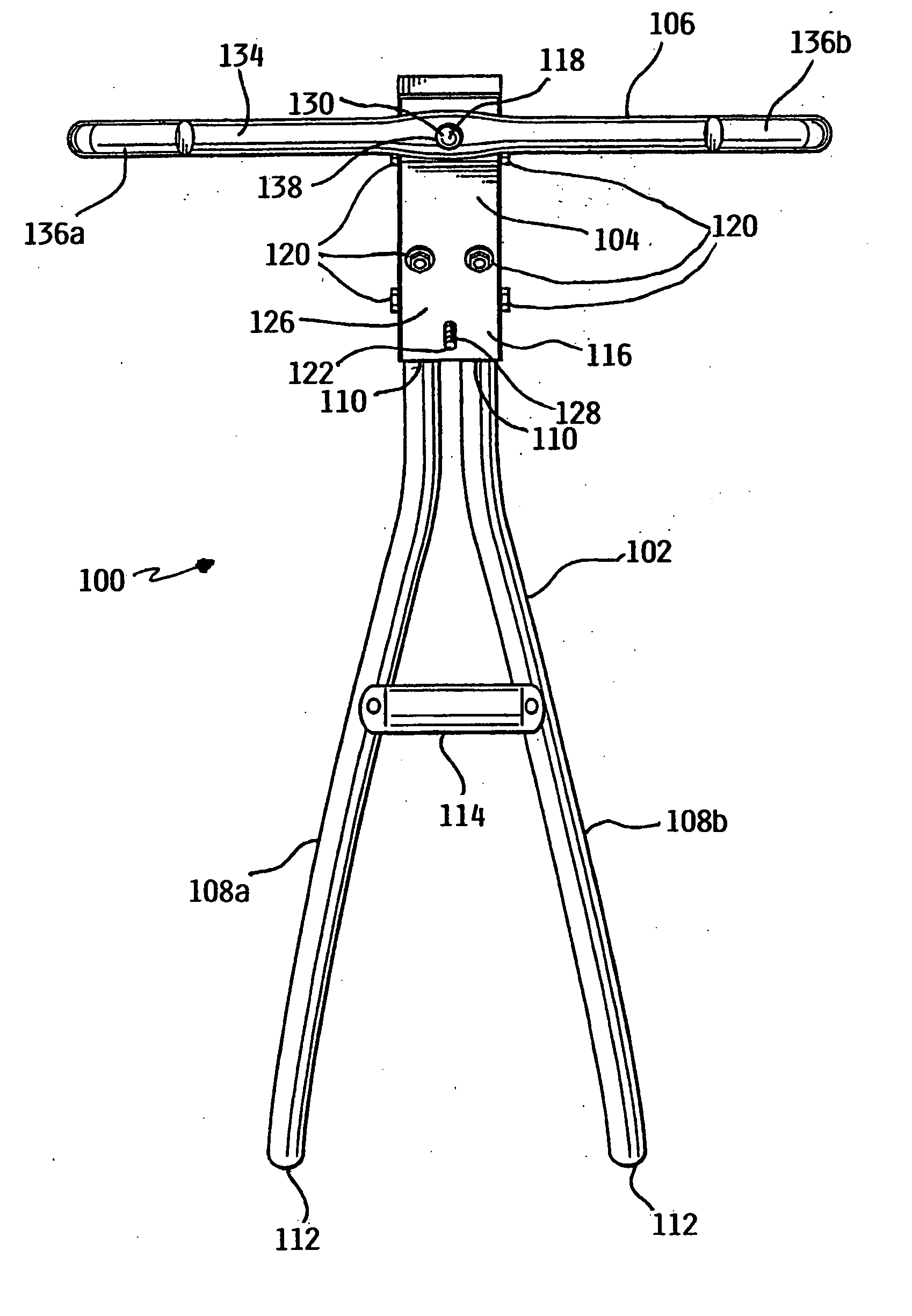
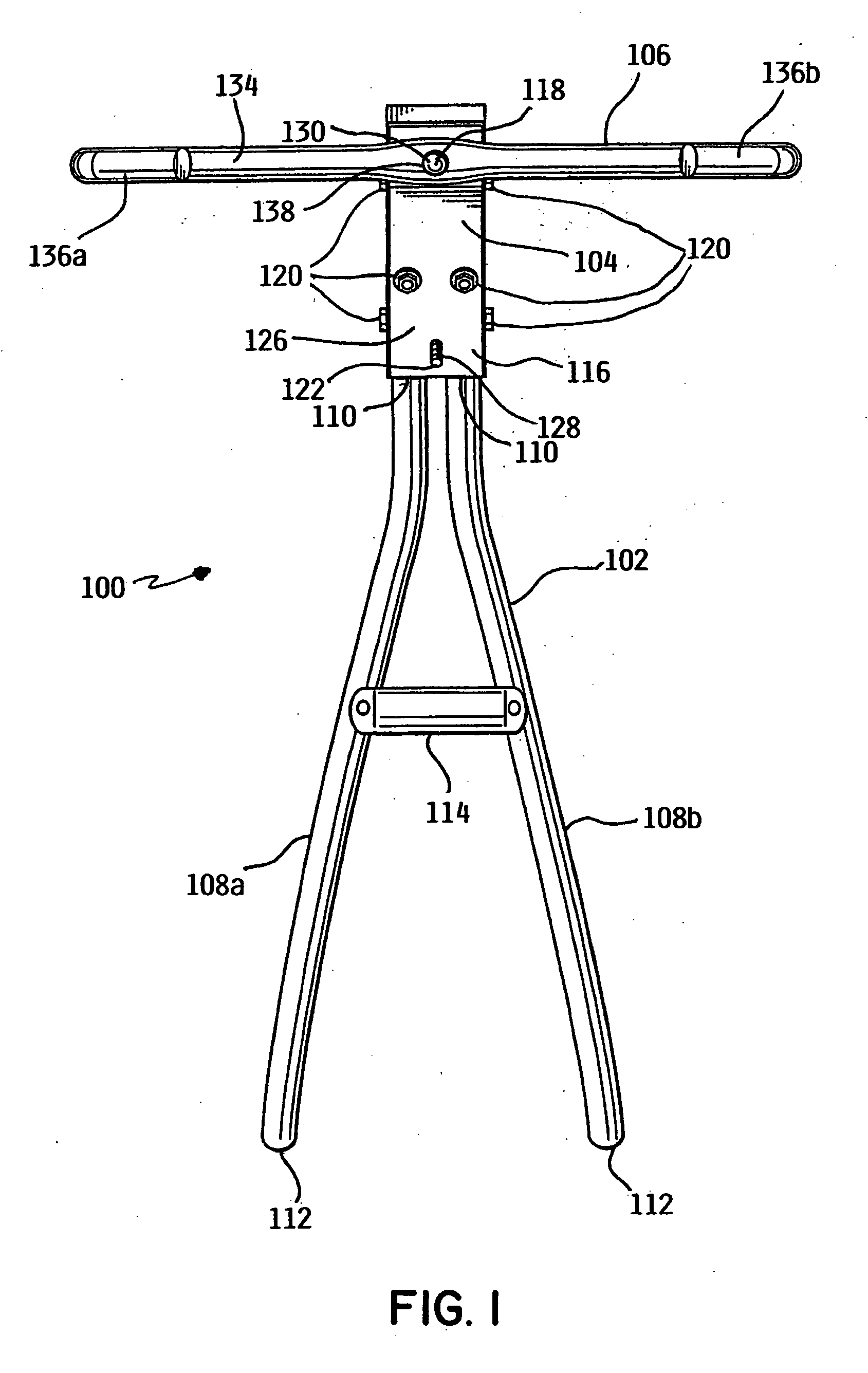
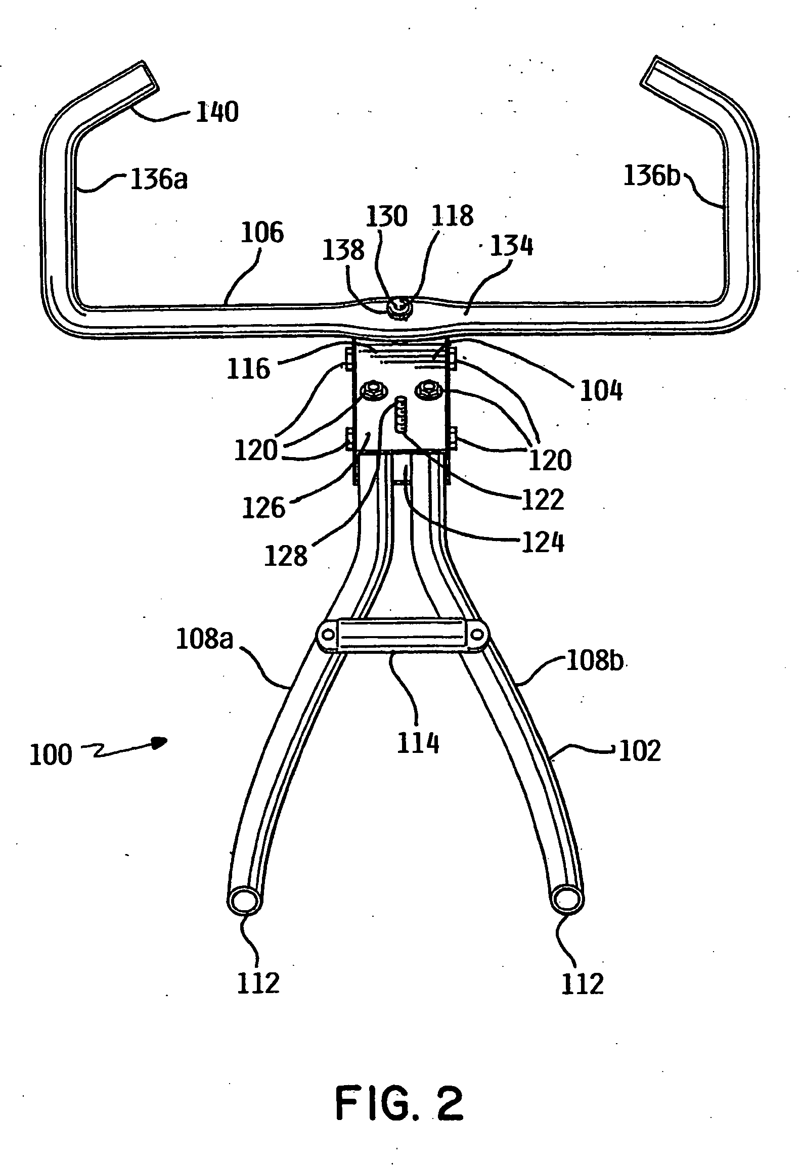
[0025] As illustrated in FIGS. 1, 2, 3, 4 and 5, a first embodiment of a handlebar assembly 100 for use with a push apparatus can comprise a support frame 102, a pivot assembly 104, and a handlebar member 106. Handlebar assembly 100 can be fabricated and operably joined using suitable methods of fabrication including the use of appropriate fasteners, welding, molding and combinations thereof. Handlebar assembly 100 can further comprise suitable materials of construction such as, for example, metals including carbon steel and aluminum, plastic polymers, wood and combinations thereof. Depending upon the style and function of the push apparatus, handlebar assembly 100 can be fabricated to have desirable properties including, for example, being a lightweight design, a heavy-duty design or having desirable aesthetic properties.

[0026] Referring to FIGS. 1-5, support frame 102 can comprise two side support members 108a and 108b, though it is envisioned that support frame 102 could also co...


PUM


Abstract

A handlebar assembly and related methods for utilizing the handlebar assembly with a push apparatus. The handlebar assembly includes handlebars pivotally mounted to a support frame, which in turn is coupled to the push apparatus. The handlebar assembly can be utilized with a variety of different push apparatus including either user propelled or self-propelled push lawnmowers. The handlebar assembly can incorporate additional user control features such as a hand operated throttle control or brake assembly. Through the use of the handle bar assembly, the push apparatus can be propelled or otherwise directed in a continuous motion such that stopping and pivoting movements are not required to change the operating direction of the push apparatus. The handlebar assembly allows for an increase in exercise intensity while simultaneously providing improved turning control to the push apparatus.

Description

PRIORITY CLAIM [0001] The present invention claims priority to U.S. Provisional Application Ser. Nos. 60 / 707,649 filed Aug. 12, 2005, entitled “HANDLEBAR ASSEMBLY FOR PUSH APPARATUS” and 60 / 816,395 filed Jun. 23, 2006, entitled “HANDLEBAR ASSEMBLY FOR PUSH APPARATUS”, both of which are herein incorporated by reference in their entirety.FIELD OF INVENTION [0002] The present invention relates generally to a handlebar assembly. More particularly, the invention relates to a pivoting handlebar assembly for use with a push apparatus. BACKGROUND OF INVENTION [0003] In today's fast-paced society, it is often times difficult to find time to exercise during the day. In addition, the job force has become increasingly sedentary. Sedentary jobs, such as, for example, desk jobs, provide little or no physical activity during the course of the day. In addition, ordinary household chores, such as, for example, mowing the lawn, that were once a source of physical activity and exercise, have been made...

Claims


Application Information

Patent Timeline
IPC IPC(8): A63B22/00
CPCA63B21/0618A63B21/1434A63B22/20A63B23/047Y10T16/499A63B2069/0037A63B2208/0204B62B5/06B62B9/20A63B69/0028A63B21/4017
Inventor COFRIN, MICHAEL
Owner COFRIN MICHAEL
Why Eureka
Try Eureka