Bath drain closure assembly

a technology for drain closures and bathtubs, applied in water installations, domestic plumbing, construction, etc., can solve the problems of overly expensive manufacture, installation, or repair, and other problems, and achieve the effect of reducing the number of problems, and avoiding the need for maintenan

Inactive Publication Date: 2007-02-22
WCM IND INC
View PDF4 Cites 41 Cited by
  • Summary
  • Abstract
  • Description
  • Claims
  • Application Information

AI Technical Summary

Problems solved by technology

While such drain closures work well, they are not convenient to operate because they are located on the bottom of the bathtub where the drain is located.
However, valves of this type usually suffer from one or more of the following deficiencies: (1) they subject electrical par...

Method used


Image

  • Bath drain closure assembly
  • Bath drain closure assembly
  • Bath drain closure assembly

Examples


Embodiment Construction

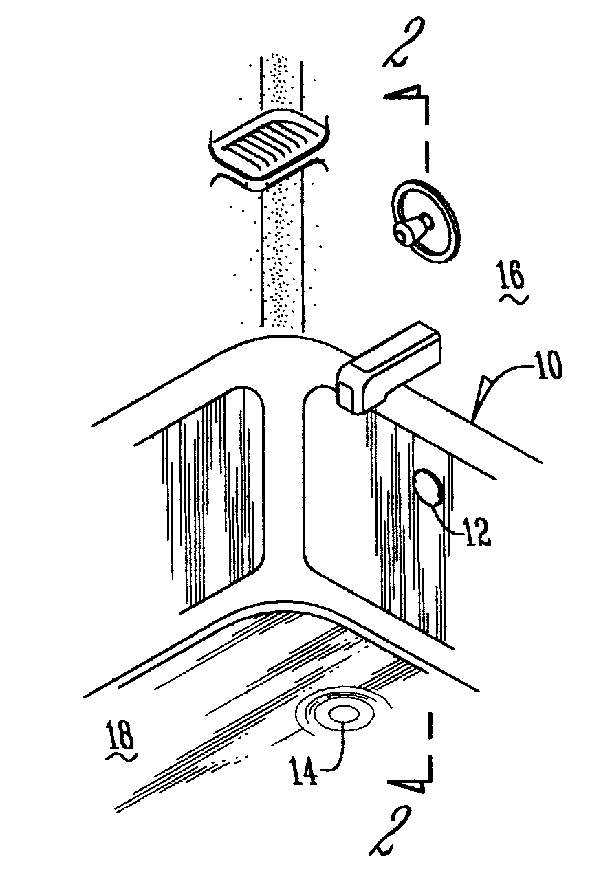
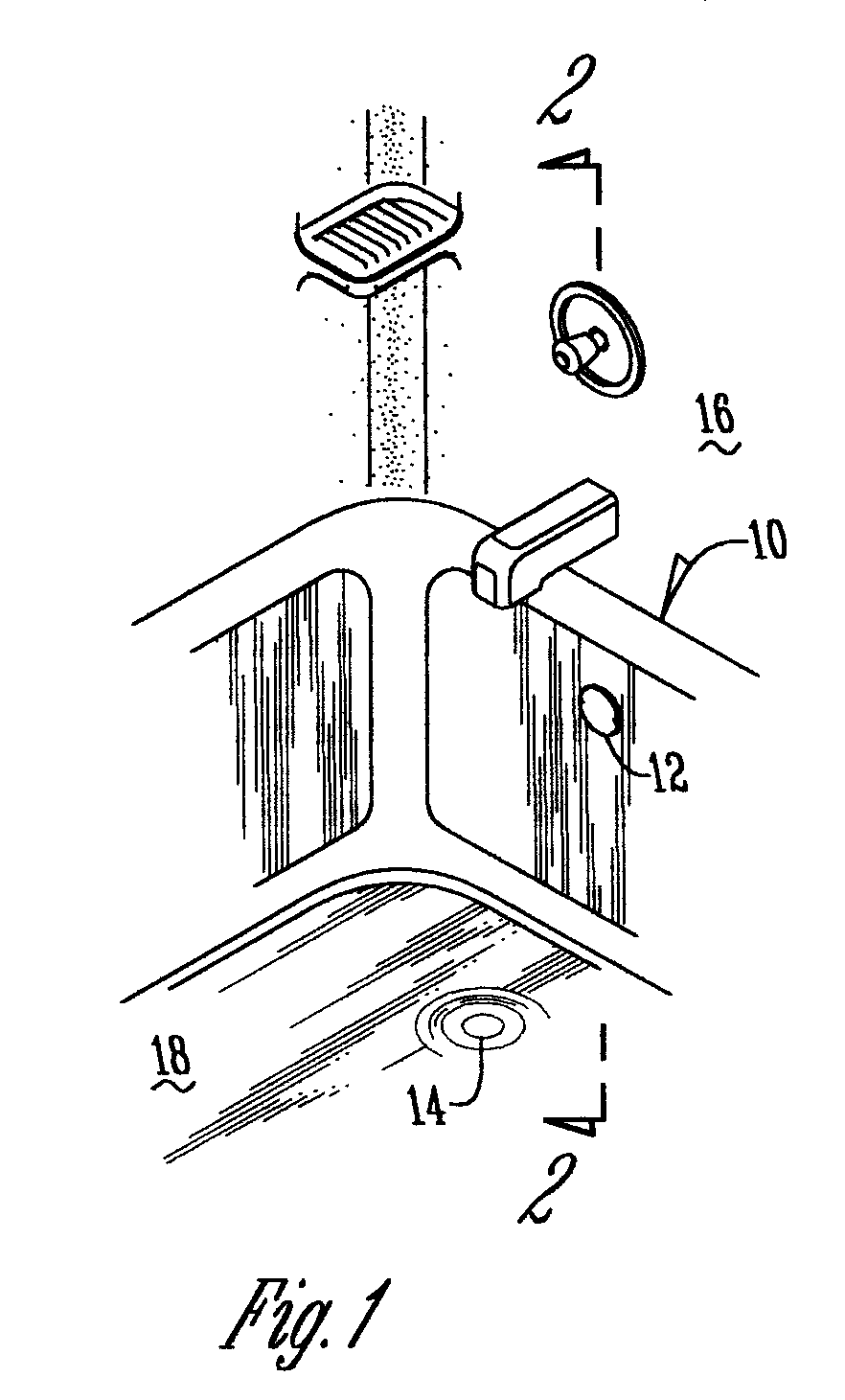
[0014] With reference to FIGS. 1 and 2, a conventional bathtub 10 has an upper overflow drain 12 and a lower drain 14. The upper overflow drain 12 is located at one end wall 16 of the bathtub 10 for draining overflow fluids from the bathtub 10. The lower drain 14 is located in the bottom 18 of the bathtub 10 for draining fluids from the bottom of the bathtub 10.

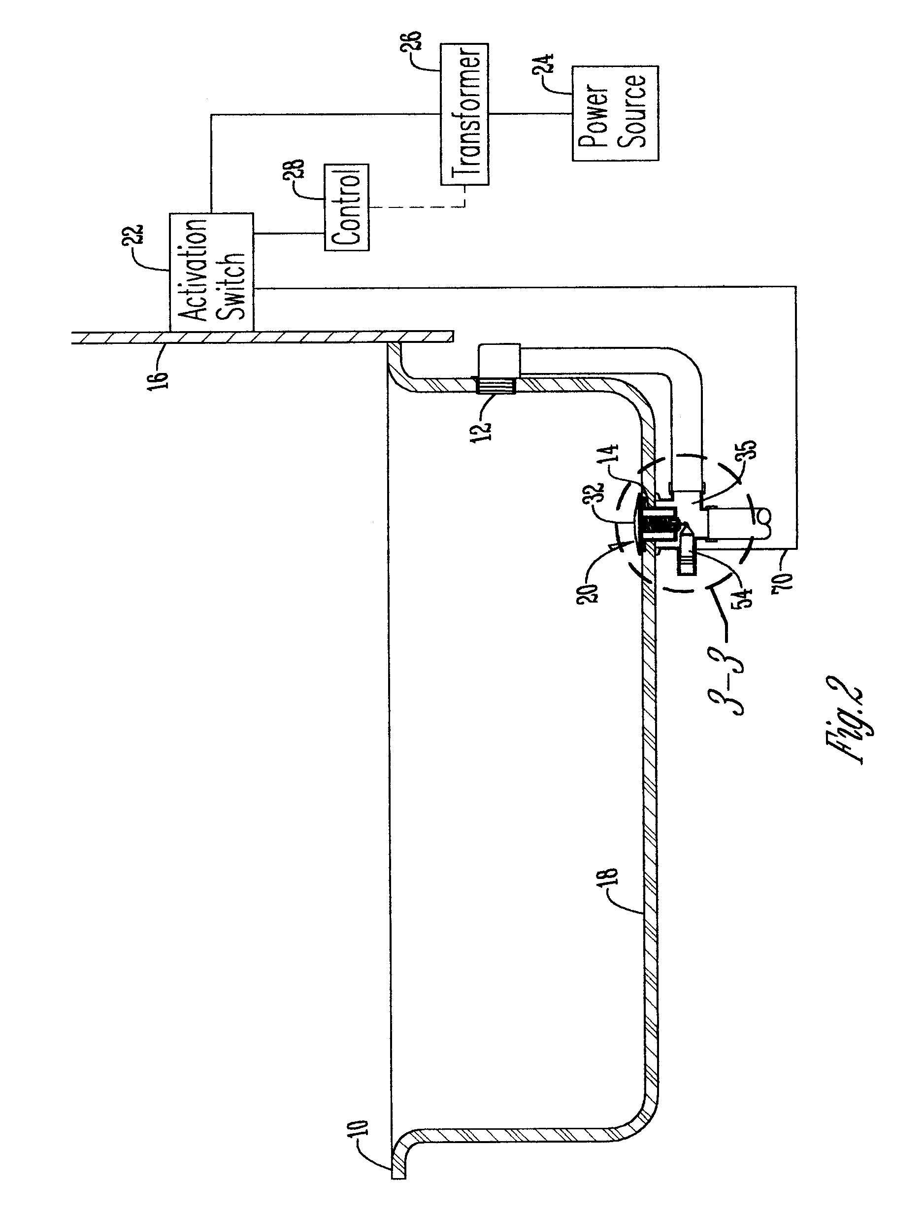
[0015] The bath drain closure assembly 20 is mated with the lower drain 14 to open and close the drain 14 to allow and prevent fluid flow. An activation switch 22 is preferably located in the end wall 16 of the bathtub 10 and is electronically connected to the drain closure assembly 20. Alternatively, the activation switch 22 is located on a far wall or deck of the tub. The activation switch 22 allows a user to selectively activate the drain closure assembly 20 to open and close drain 14.

[0016] A power source 24 is connected to the activation switch 22 to provide power to the drain closure assembly 20 through the activation...


PUM


Abstract

A drain closure assembly for use with a bathtub, having a drain closure device with a stopper positioned above a lower drain and a plunger device attached to the stopper adapted to bias the stopper in a downward direction. An actuating mechanism received within a housing in communication with a conduit extending from the lower drain, the actuating member having a main body that contacts the drain closure device and moves the drain closure device to an open position when activated and a closed position when deactivated.

Description

BACKGROUND OF THE INVENTION [0001] This invention relates to a bathtub drain closure assembly. More particularly, this invention relates to a bath drain closure device that is opened and closed by an electronic activating member. [0002] Bathtub drains commonly have a closure valve therein which can open or close the drain by being lifted manually upward to open the drain or drop to an initial seating position to close the drain. While such drain closures work well, they are not convenient to operate because they are located on the bottom of the bathtub where the drain is located. [0003] Further, there have been some prior automated bathtub drain valves. However, valves of this type usually suffer from one or more of the following deficiencies: (1) they subject electrical parts and / or connections to a risk of fluid contact by positioning the electrical parts and / or connections within the valve housing; and / or 2) they are overly expensive to manufacture, install, or repair. While thes...

Claims


Application Information

Patent Timeline
IPC IPC(8): E03C1/23
CPCE03C1/23
Inventor BALL, WILLIAM T.
Owner WCM IND INC
Why Eureka
Try Eureka