
Datachable plug coupling provided with an additional locking element

Active Publication Date: 2007-02-22
A RAYMOND & CO
View PDF9 Cites 21 Cited by
  • Summary
  • Abstract
  • Description
  • Claims
  • Application Information

AI Technical Summary

Benefits of technology

[0006] This objective is substantially solved by the present invention which can be pressed without problem onto the head of the coupling housing in the axial direction and easily shifted into the locking position after the establishment of the coupling connection with the insertion part. In this process, it is ensured by m

Problems solved by technology

This locking element, in its constructive design, is unsatisfactory because it requires, for its attachment and to achieve the desired locking effect to the coupling housing, various constructive changes and adaptations.
In addition, the manufacture of the hinge connection also requires an additional work step that increases the manufacturing cost of the entire plug coupling.
Finally, it is considered a drawback that the catch prior to the pivoting projects transversely upward and thus occupies a large amount of space in the open position.

Method used


Image

  • Datachable plug coupling provided with an additional locking element
  • Datachable plug coupling provided with an additional locking element
  • Datachable plug coupling provided with an additional locking element

Examples


Embodiment Construction

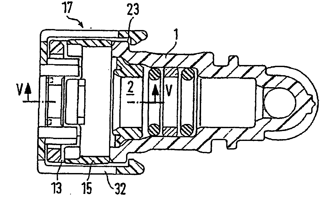
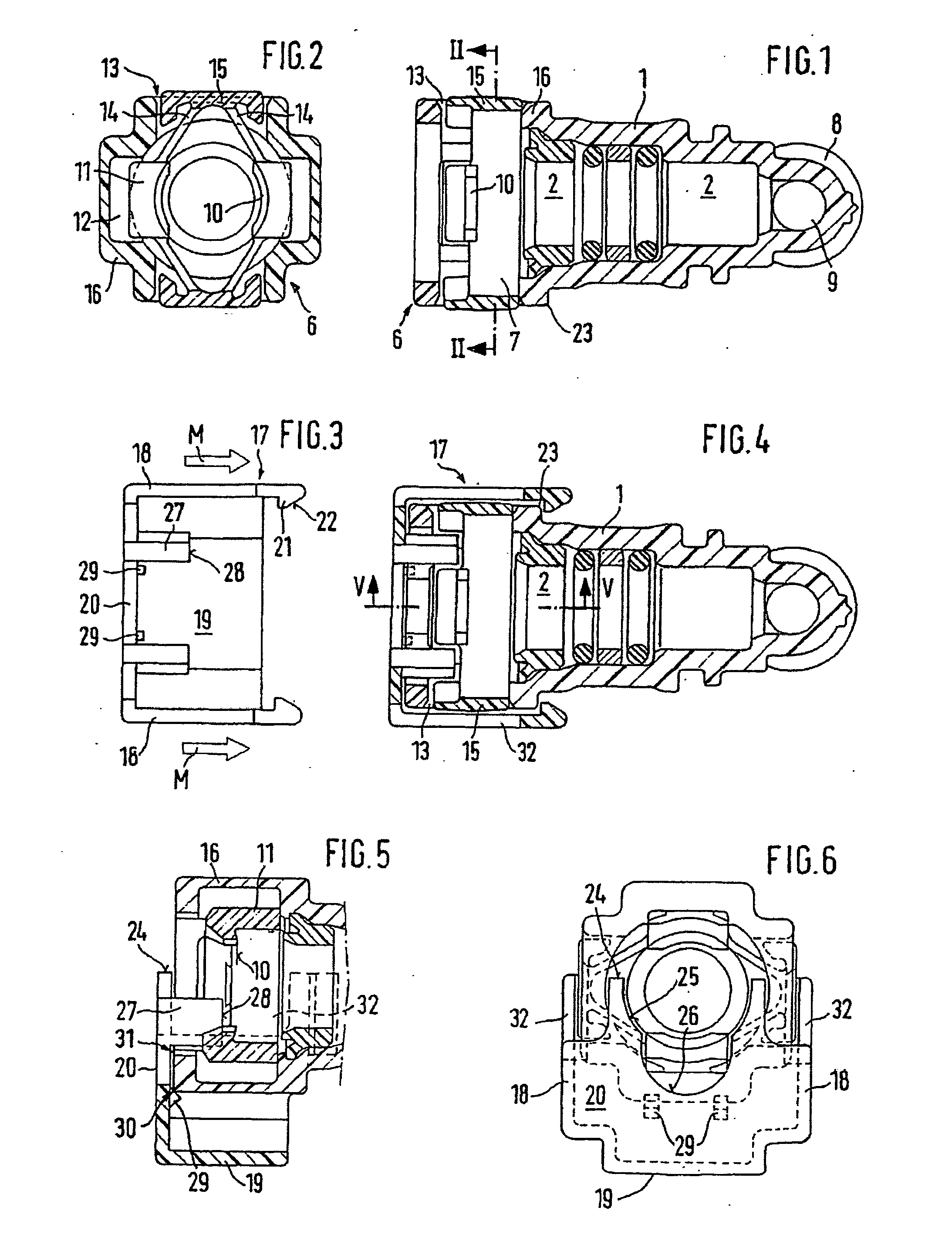
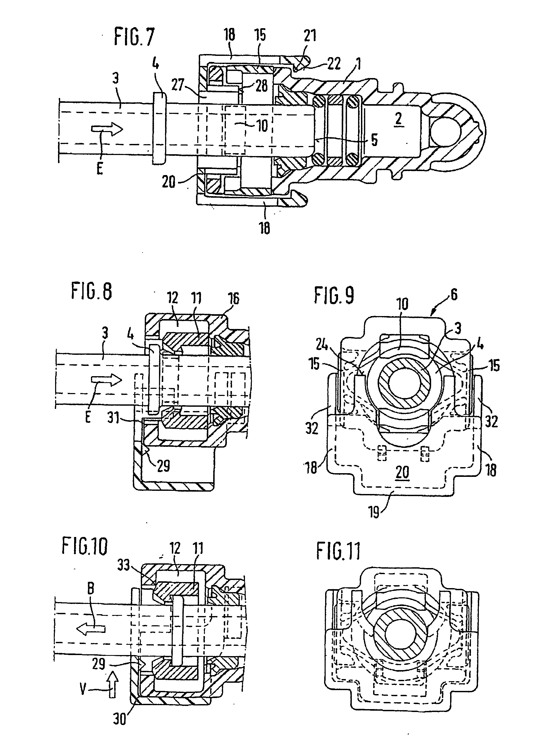
[0020] The plug coupling represented in the figures is substantially comprised of a coupling housing 1 with a cylindrical accommodating space 2 for the insertion of a tubular insertion part 3 at a spaced distance from the opening end 5, wherein the tubular insertion part 3 includes a circumferential retention rib 4 (see also FIG. 7). The coupling housing 1 is formed with an enlarged housing head 6, which receives a separate retention element 7. The end of the accommodating space 2 is connected to the coupling housing 1 by means of a connecting adapter 8 having an outlet opening 9 through which the fluid conveyed through the coupling can continue to flow into a fluid line which is not shown.

[0021] The holding element 7 is provided with retaining edges 10 that can be elastically opened and are oriented radially into the accommodating space 2. The retaining edges are pressed away from one another by the retaining rib 4 during the pressing of the insertion part 3 into the accommodating...


PUM


Abstract

The detachable plug coupling serves to connect liquid lines, particularly fuel lines of motor vehicles. The plug coupling is provides a tubular insertion part (3) with an encircling remaining rib (4) and a coupling housing (1) with a cylindrical accommodating space (2) for the insertion part (3). The plug coupling also has an enlarged head part (6) with a separate retaining element (7), which is provided with elastically opening retaining edges (10). The retaining edges are radially directed into the accommodating space (2) and engage behind the retaining rib (4) after the insertion part (3) has been pushed in. In order to ensure that the retaining rib (4) is correctly snapped in behind the retaining edges (10) after the insertion part (3) has been inserted, an additional locking element (17) is provided, which is guided in a transversally displaceable manner on the housing head (6) between an opening position and a closing position.

Description

RELATED APPLICATIONS [0001] This application is the U.S. national phase of International Application No. PCT / EP02 / 03076 filed 20 Mar. 2002, which claims priority of German Application No. 101 15 399.6 filed 29 Mar. 2001.FIELD OF THE INVENTION [0002] The invention relates to a detachable plug coupling with an additional locking element for the connection of fluid lines. Such plug couplings are used in the construction of motor vehicles to connect fuel lines to each other or to a fuel reservoir or distributor. BACKGROUND OF THE INVENTION [0003] Such a plug coupling with an additional locking element is known, for example, from WO 96 / 34224. The locking element is here designed as a catch which is attached in a manner so it can be pivoted via a hinge which is formed on the external surface of the coupling housing. A locking tongue is formed on the catch which, during engagement by pivoting of the catch after the engagement of the insertion part, is arranged between a slit trap which rea...

Claims


Application Information

Patent Timeline
IPC IPC(8): F16L39/00F16L37/084B60R16/08F16L37/12
CPCF16L37/0841F16L37/088F16L37/0985F16L2201/10F02M37/0017F02M55/004F02M2200/853F02M2200/8023F16L37/0885F16L37/084
Inventor MORETTI, ERMINIOMARTIN-COCHER, DANIEL
Owner A RAYMOND & CO
Learn More