Apparatus and method for providing differential protection for a phase angle regulating transformer in a power system

a technology of differential protection and transformer, applied in emergency protective circuit arrangements, instruments, measurement devices, etc., can solve the problems of high sensitiveness, difficult to apply differential elements to par transformers, and not all power transformers however operate to step

Active Publication Date: 2007-02-22
SCHWEITZER ENGINEERING LABORATORIES
View PDF8 Cites 37 Cited by
  • Summary
  • Abstract
  • Description
  • Claims
  • Application Information

AI Technical Summary

Benefits of technology

[0018] It should be understood that the present invention includes a number of different aspects and / or features which may have utility alone and / or in combination with other aspects or features. Accordingly, this summary is not an exhaustive identification of each such aspect or feature that is now or may hereafter be claimed, but represents an overview of certain aspects of the present invention to assist in understanding the more detailed description that follows. The scope of the invention is not limited to the specific embodiments described below, but is set forth in the claims now or hereafter filed.

Problems solved by technology

In addition, because the differential relay operates on the difference current rather than only on the through current in the system, it is highly sensitive.
Not all power transformers however operate to step-up or step-down voltage.
Unfortunately, unlike application to typical power transformers, application of differential elements to PAR transformers is often difficult due to the continuously variable phase angles of the measured currents between the source- and load-side of the PAR transformer.
In fact, a small difference in phase angle may translate into a large operate current thereby rendering the differential relay unsuitable for its intended application.
Thus, under external (through-fault) conditions, the currents entering and exiting the transformer cannot be easily balanced thereby causing the differential elements to incorrectly trip for an external fault.
Thus, traditional transformer differential protection cannot be effectively applied to a PAR transformer.

Method used


Image

  • Apparatus and method for providing differential protection for a phase angle regulating transformer in a power system
  • Apparatus and method for providing differential protection for a phase angle regulating transformer in a power system
  • Apparatus and method for providing differential protection for a phase angle regulating transformer in a power system

Examples


Embodiment Construction

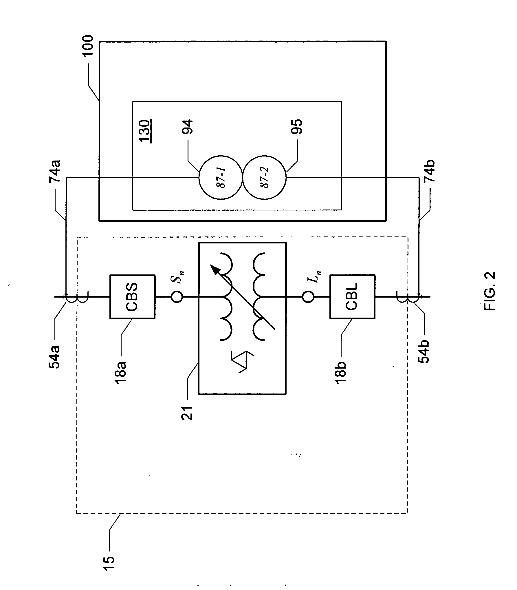
[0025] An apparatus and method is provided in a protective device to compensate for a phase shift introduced by operation of the PAR transformer, operatively coupled to the protective device, in order to allow application of current differential protection to the PAR transformer.

[0026] For ease of discussion, aspects of the present invention can be more fully understood by limiting the detailed discussion to a protection zone that includes one phase angle regulating transformer monitored by a differential relay, coupled to the protection zone via a number nn of current transformers. Such a protection zone is defined herein to include the A-phase, B-phase and C-phase primary currents flowing into the phase angle regulating transformer at each terminal. Further, the apparatus and methods disclosed herein are also applicable to other power system devices such as lines and power transformers.

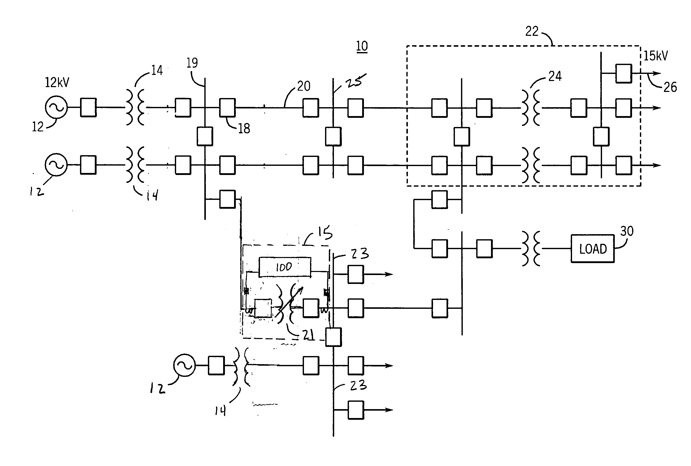
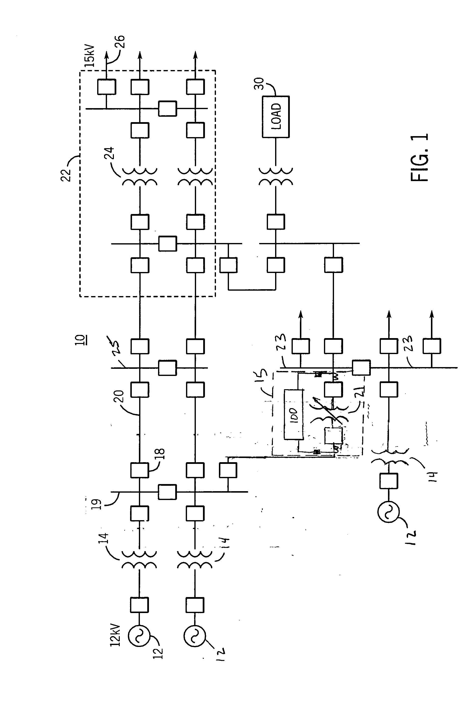
[0027]FIG. 1 is a single line schematic diagram of a power system 10 that may be utilized in a...


PUM


Abstract

Provided is an apparatus and method for providing differential protection for a phase angle regulating transformer having a load side and a source side in a three-phase power system. The method includes calculating a first positive sequence component and a first negative sequence component associated with incoming secondary currents detected on the source side, calculating a second positive sequence component and a second negative sequence component associated with outgoing secondary currents detected on the load side, applying a phase angle shift to the second positive sequence component and the second negative sequence component to form a compensated positive sequence component and a compensated negative sequence component, respectively, and determining an operate current value and a restraint current value for each of a positive and negative sequence differential element of the differential protection based on the compensated positive sequence component and the compensated negative sequence component.

Description

CROSS-REFERENCE TO RELATED APPLICATIONS [0001] None BACKGROUND OF THE INVENTION [0002] The present invention generally relates to power system protection, and more specifically, to an apparatus and method for providing differential protection for a phase angle regulating transformer in a power system. [0003] Electric utility systems or power systems are designed to generate, transmit and distribute electrical energy to loads. In order to accomplish this, power systems generally include a variety of power system elements such as electrical generators, electrical motors, power transformers, power transmission lines, buses and capacitors, to name a few. As a result, power systems must also include protective devices and procedures to protect the power system elements from abnormal conditions such as electrical short circuits, overloads, frequency excursions, voltage fluctuations, and the like. [0004] Protective devices and procedures act to isolate some power system element(s) from the...

Claims


Application Information

Patent Timeline
Patent Type & Authority Applications(United States)
IPC IPC(8): H02H3/00
CPCH02H3/286H02H7/045
Inventor THOMPSON, MICHAEL J.
Owner SCHWEITZER ENGINEERING LABORATORIES
Why Eureka
Try Eureka