
Cardiac electrode assembly

a technology of electrodes and cardiac electrodes, applied in the field of cardiac electrode assemblies, can solve the problems of limited epicardium of the heart, tortuous path limiting the ability to place such electrodes, and limitations of percutaneous delivery of cardiac electrodes

Inactive Publication Date: 2007-02-22
ACORN CARDIOVASCULAR
View PDF11 Cites 12 Cited by
  • Summary
  • Abstract
  • Description
  • Claims
  • Application Information

AI Technical Summary

Problems solved by technology

Notwithstanding advantages, percutaneous delivery of cardiac electrodes has limitations.
Such vasculature has a narrow diameter and often presents a tortuous path limiting the ability to place such electrodes.
Further, even if an electrode can be advanced into the coronary vasculature, only a very limited surface area of the epicardium of the heart can be treated in this manner.
Percutaneously accessible blood vessels may not be overlying the most desirable area of the heart for treatment.
Paired electrodes such as the CapSure® Epi electrode assembly also have certain limitations.
A previously placed electrode may no longer be in optimal location and the patient must either cope with sub-optimal pacing or endure a subsequent procedure for re-positioning of electrodes.

Method used


Image

  • Cardiac electrode assembly
  • Cardiac electrode assembly
  • Cardiac electrode assembly

Examples


Embodiment Construction

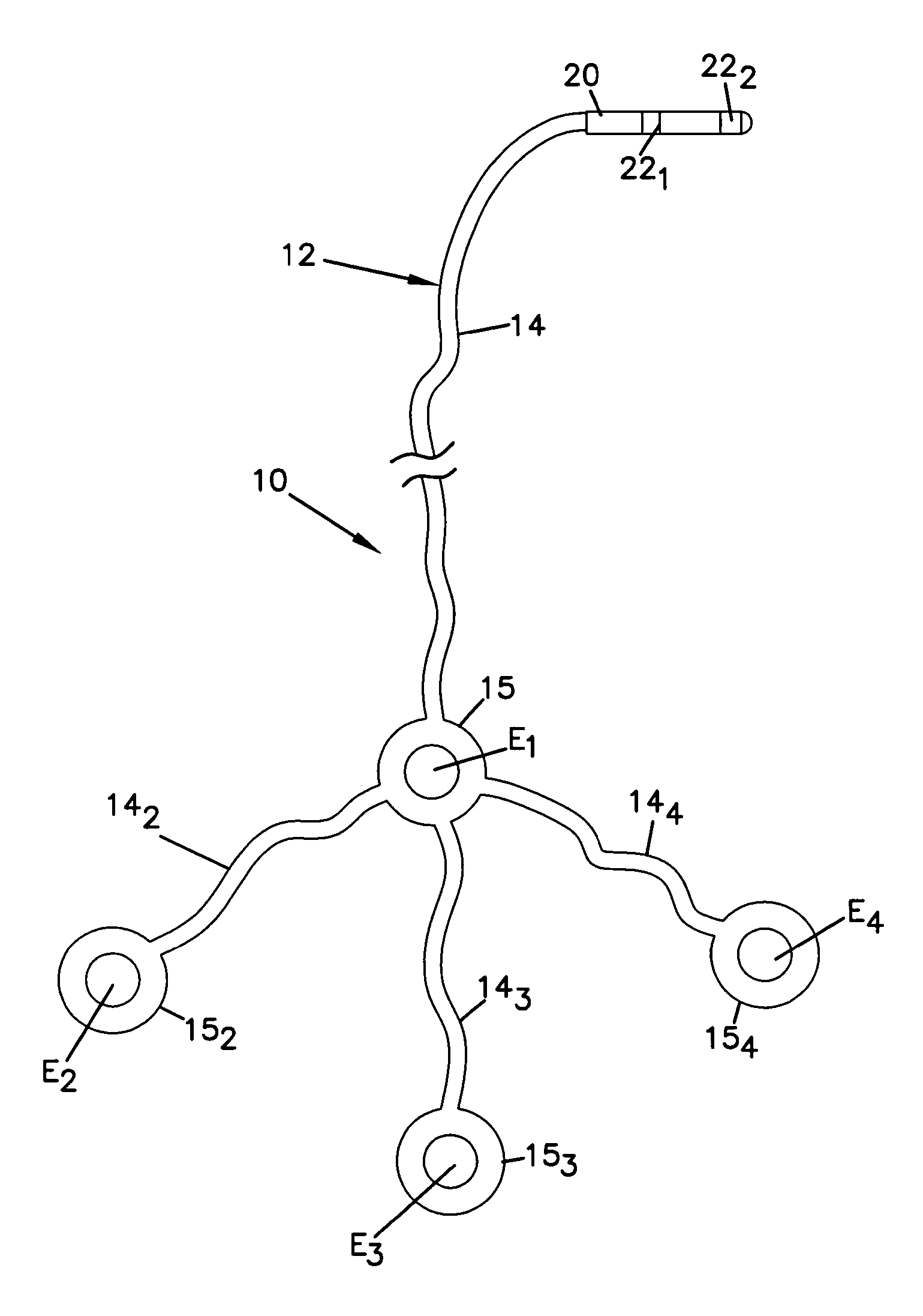
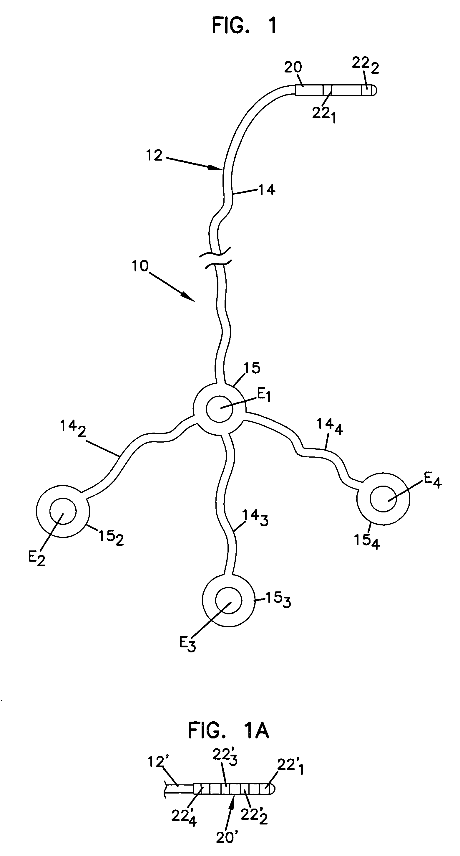
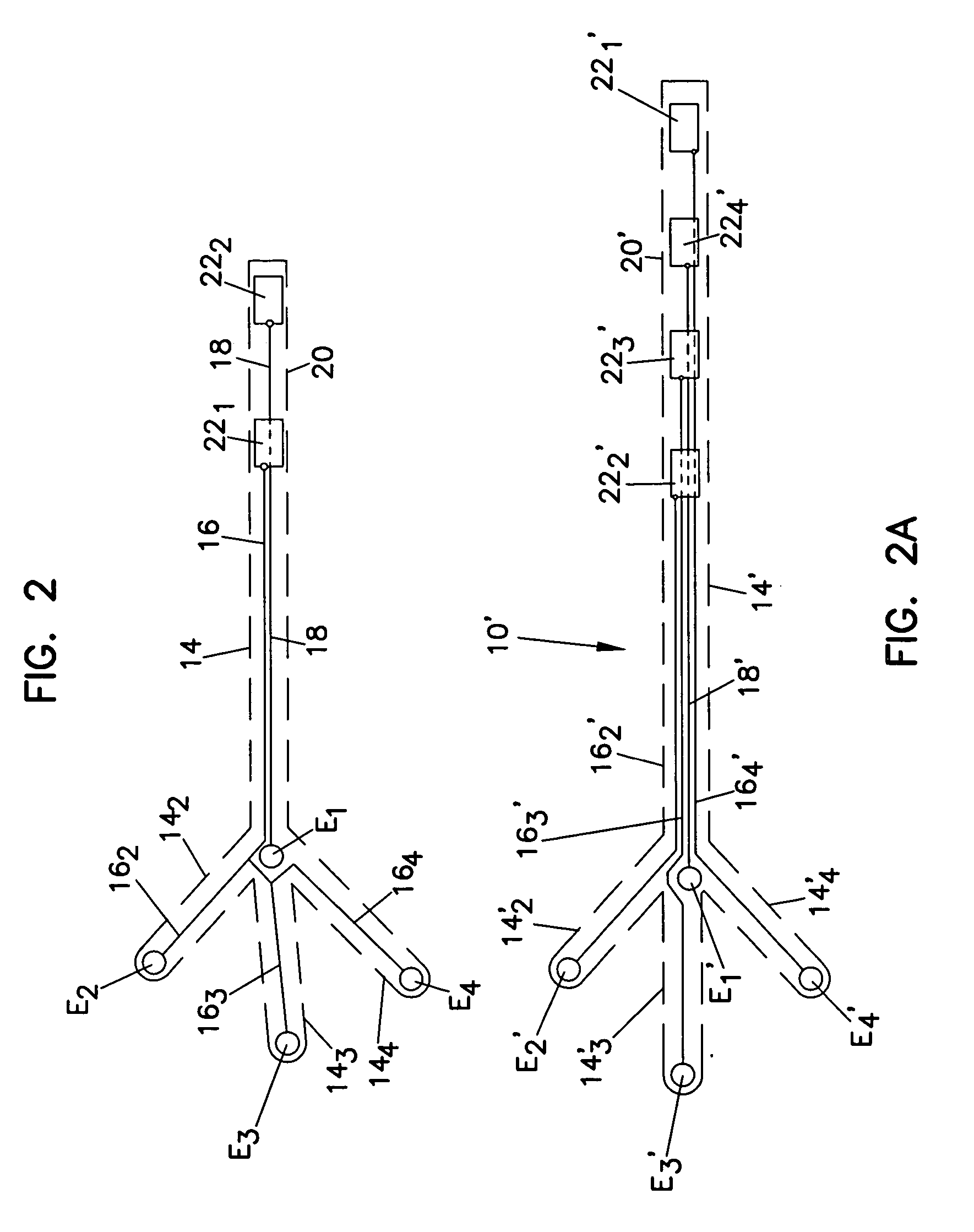
[0033] With reference now to the various drawing figures in which identical elements are numbered identically throughout, a description of a preferred embodiment of the present invention will now be provided. The following patents and published applications, described elsewhere in this application, are incorporated herein by reference: U.S. Pat. No. 6,907,285 issued Jun. 14, 2005; U.S. Pat. No. 6,893,392 issued May 17, 2005; U.S. Pat. No. 5,702,343 issued Dec. 30, 1997; U.S. Pat. No. 6,123,662 issued Sep. 26, 2000; U.S. Pat. No. 6,482,146 issued Nov. 19, 2002; U.S. Pat. No. 6,730,016 issued May 4, 2004; U.S. Pat. No. 6,425,856 issued Jul. 30, 2002; U.S. Pat. No. 6,572,533 issued Jun. 3, 2003; and U.S. patent application Ser. No. 10 / 165,504 filed Jun. 7, 2002 and published Dec. 12, 2003 as Publication No. 2003-0229265A1.

Novel Electrode Assembly Design for IS-1 Connector

[0034] Referring first to FIG. 1, an electrode assembly 10 according to the present invention includes a pluralit...


PUM


Abstract

A cardiac electrode assembly includes an electrode lead with a plurality of electrical conductors in a common lead jacket. The electrical conductors include a primary conductor and at least a first secondary conductor. At a proximal end of the lead, the conductors terminate at a connector having a plurality of exposed electrical contacts. The contacts include a primary contact connected to the primary conductor and a secondary contact connected to the secondary conductor. A plurality of cardiac electrodes is mechanically connected to the distal end of the lead. The plurality includes a primary cardiac electrode and at least a secondary cardiac electrode (more preferably, at least two secondary cardiac electrodes) connected to one or more secondary conductors. In still preferred embodiments of the invention, multiple secondary conductors with separate leads in the common jacket are connected to the distal end of the common lead jacket.

Description

I. BACKGROUND OF THE INVENTION [0001] 1. Field of the Invention [0002] This invention pertains to a cardiac electrode assembly for pacing, sensing or applying signals to a tissue of a heart. [0003] 2. Description of the Prior Art [0004] Cardiac electrodes have long been used on the heart for sensing electrical activity on the heart and for the treatment of a variety of disorders including cardiac asynchrony. Cardiac electrodes come in many varieties of shapes and sizes and configurations including a wide variety of features for securing the electrode to a tissue of the heart. For example, such electrodes may include so-called screw-in type or “pigtail” electrodes for burrowing into the tissue of the heart to secure the electrode on the heart. Also, electrodes can be urged against the heart to make contact with the heart surface. Such electrodes may be individually placed on the heart. Japanese Pat. No. 2271829 dated November 1990 shows electrodes for diagnosis of infarction. The ele...

Claims


Application Information

Patent Timeline
Patent Type & Authority Applications(United States)
IPC IPC(8): A61N1/05
CPCA61N1/0587
Inventor JANSSENS, HERVEWALSH, ROBERT G.PIGNATO, PAUL ANDREWTHOMAS, ANN MARGARET
Owner ACORN CARDIOVASCULAR
Learn More