Variable cutting angle hand plane

a hand plane and variable cutting technology, applied in the field of woodworking tools, can solve the problem of needing separate hand planes

Inactive Publication Date: 2007-03-01
FINE TOOLS
View PDF24 Cites 10 Cited by
  • Summary
  • Abstract
  • Description
  • Claims
  • Application Information

AI Technical Summary

Benefits of technology

[0017] Yet another aspect of the present invention is a hand plane having one or more adjustable throat plate(s) which allow the throat to adjust in size and location so that a user may optimize the throat as the angle of the adjustable frog changes and the protrusion of the iron through the throat changes.

Problems solved by technology

One problem in the prior art is that for every type of job, one needs separate hand planes to properly do the job.

Method used


Image

  • Variable cutting angle hand plane
  • Variable cutting angle hand plane
  • Variable cutting angle hand plane

Examples


Embodiment Construction

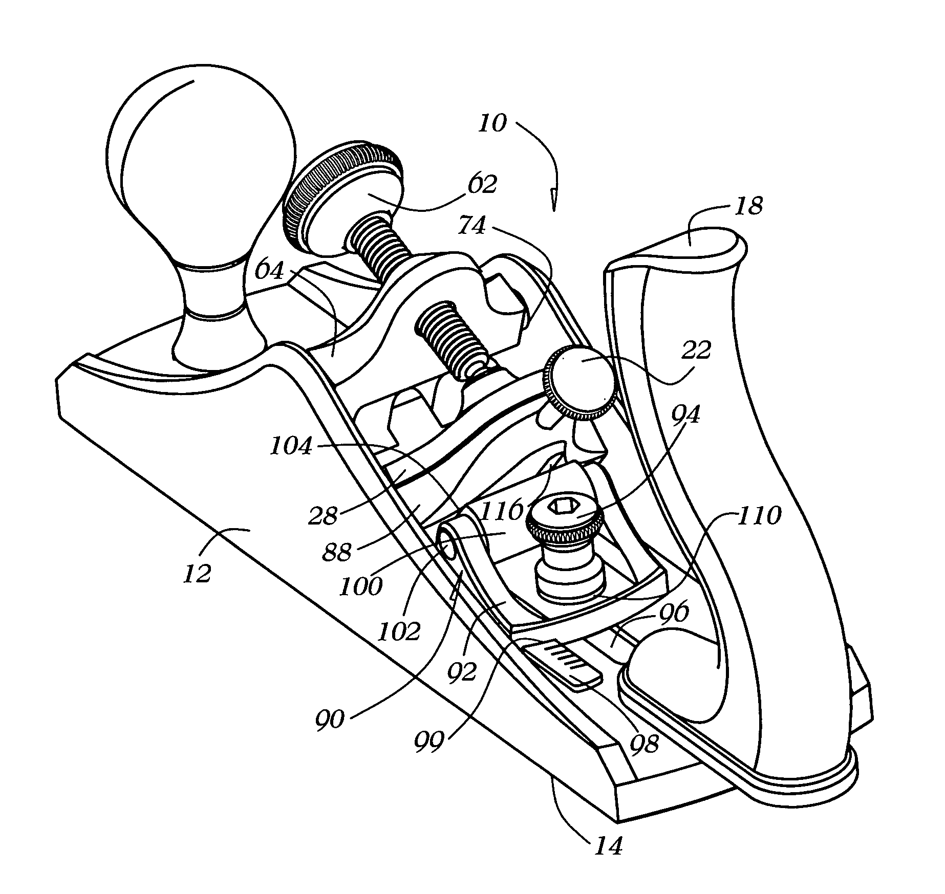
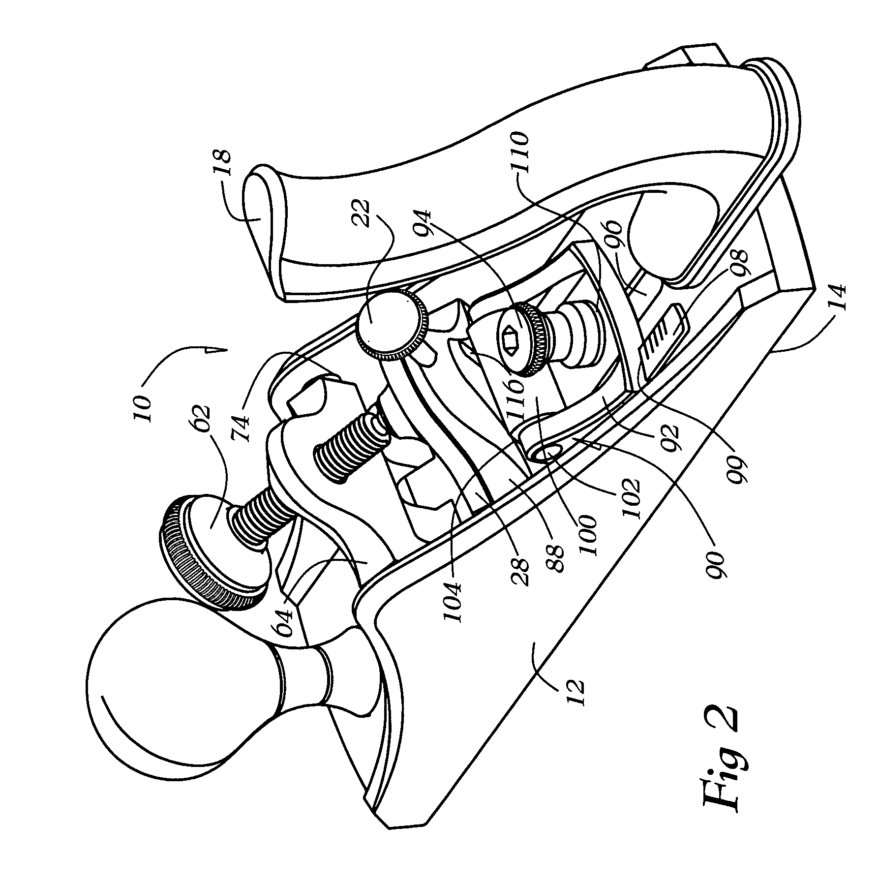
[0028] The invention is an improved hand plane. One embodiment of the invention is shown in FIGS. 2-6. This embodiment incorporates an adjustable variable angle frog assembly 86.

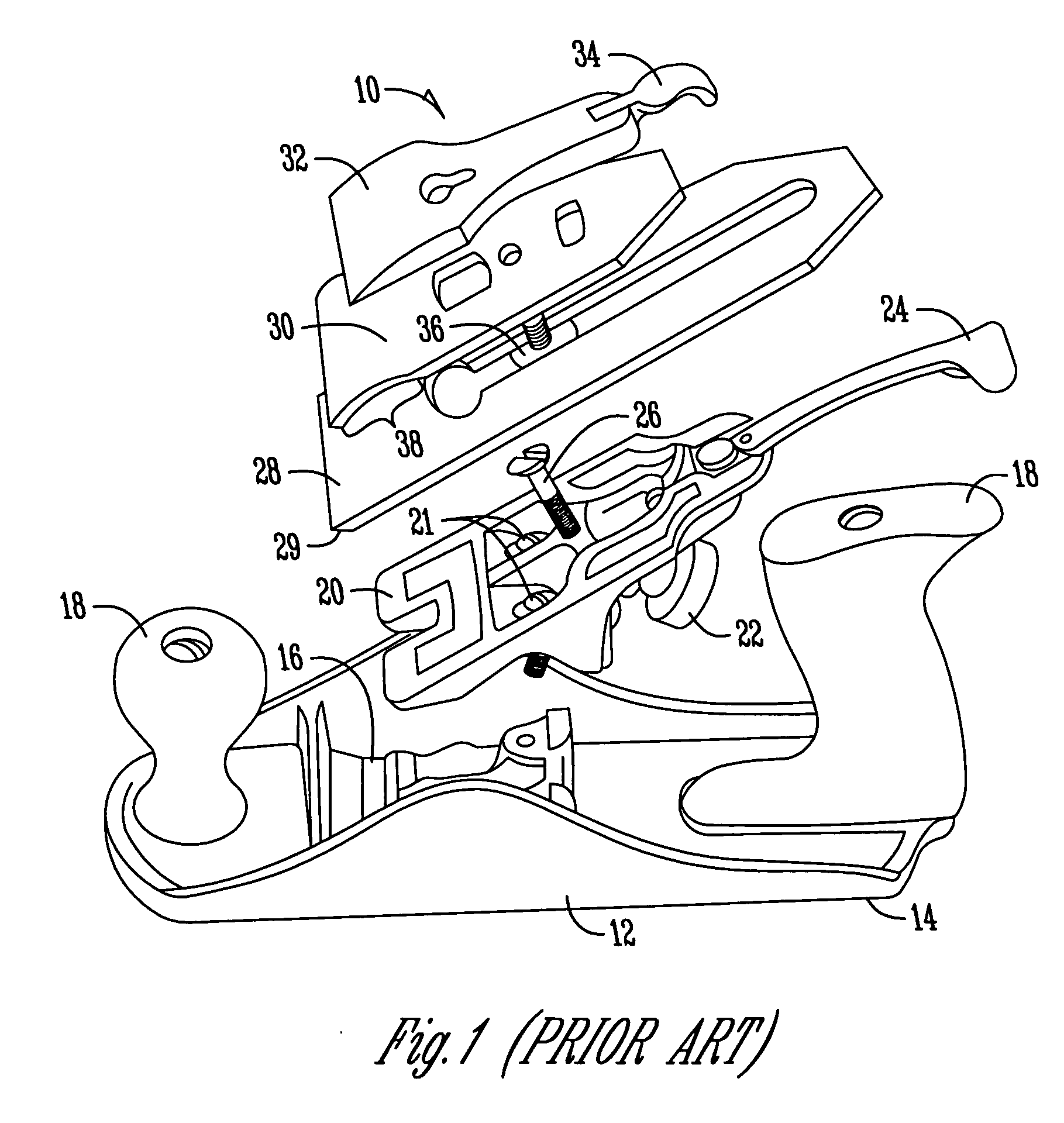
[0029] This embodiment of the invention is constructed with a base unit 12 in which the underside of the base unit 12 is called the sole 14. An opening through the sole 14, is a throat 16. The throat16 can be configured as an adjustable throat, as is common in the art. Attached to the base unit 12 is preferably one or more totes or handles 18. The totes 18 allow the user to grip the plane so they can push or pull the plane over the wood surface to be planed. The iron 28 rests on the adjustable frog 88 and extends through the throat 16. The iron 28 is held to the frog assembly 88 by an articulated iron cap assembly. The articulated iron cap assembly is constructed with an iron cap main body 64 which pivotally mounts to the base unit 12 by the iron cap assembly main pivots 74. These iron cap assembly main piv...


PUM


Abstract

A variable cutting angle hand plane is provided. The variable cutting hand plan has a base unit configured for holding an iron, wherein the base unit has a sole and a throat extending through the base unit to the sole. The base unit has an adjustable frog for supporting the iron at multiple angles with respect to the sole. A means for engaging the iron is used for holding the iron against the adjustable frog. The hand plane may have an adjustable throat. There may be a means for indicating the approximate angle of the adjustable frog.

Description

BACKGROUND OF THE INVENTION [0001] This invention relates to woodworking tools. Specifically, this invention relates to a variable cutting angle hand plane. [0002] Hand planes have been used for hundreds of years to smooth the surface of wood. A hand plane works when a woodworker pushes or pulls the plane across the surface of the wood which allows the sharp blade of the plane iron to engage the wood and shear off a thin layer of wood, thereby smoothing the wood surface. [0003]FIG. 1 shows an expanded view of a prior art hand plane. The hand plane assembly 10 has a base unit 12, in which the bottom of the base unit 12 is the sole 14. In addition, the base unit 12 has an opening in the sole 14 which is called the throat 16. Attached to the base unit 12 is at least one handle or tote 18. A device called a frog 20 extends upward from the inside of the base unit 12. The frog 20 rigidly screws to the base unit 12 with two mounting screws 21. The frog 20 holds the blade or cutter which is...

Claims


Application Information

Patent Timeline
Patent Type & Authority Applications(United States)
IPC IPC(8): B27G17/02
CPCB27G17/02
Inventor ECONOMAKI, JOHN J.
Owner FINE TOOLS
Why Eureka
Try Eureka