Antenna distribution system

Inactive Publication Date: 2007-03-01
PJB TECH
View PDF9 Cites 2 Cited by
  • Summary
  • Abstract
  • Description
  • Claims
  • Application Information

AI Technical Summary

Benefits of technology

[0020] In another aspect of the invention, a wireless communication system is disclosed. The wireless communication system comprises a ceiling grid and an antenna distribution system with an antenna means to function as an antenna for wireless communication signal propagation. The antenna means is used in conjunction with t

Problems solved by technology

However, indoor wireless communications present several challenges for the placement of these wireless components.
This placement dependency varies with the frequency and power of transmission but in general is characterized by inadequate coverage of the cells creating “dead zones” within the demised premises, signal fading due to propagation anomalies of

Method used


Image

  • Antenna distribution system
  • Antenna distribution system
  • Antenna distribution system

Examples


Embodiment Construction

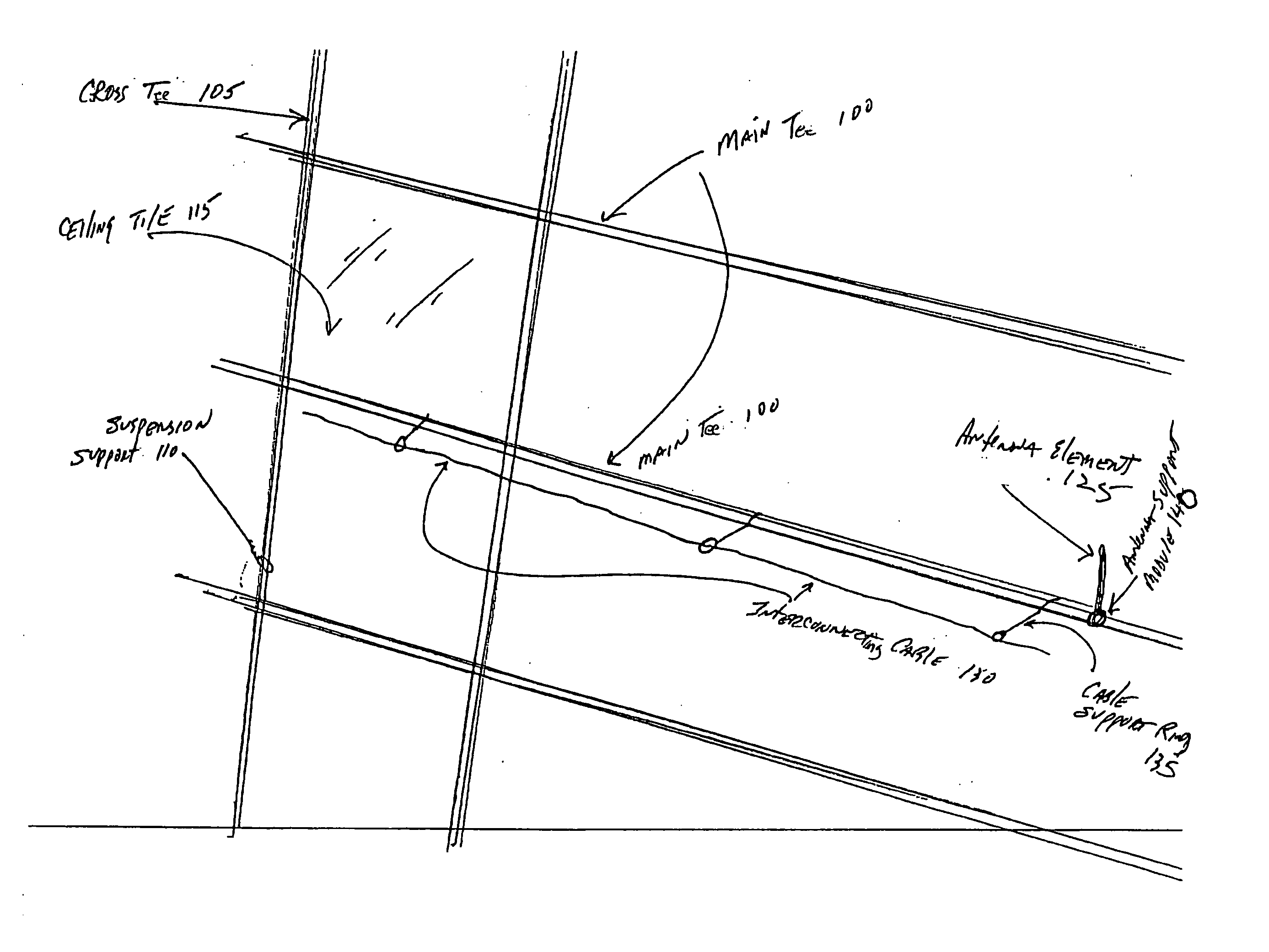
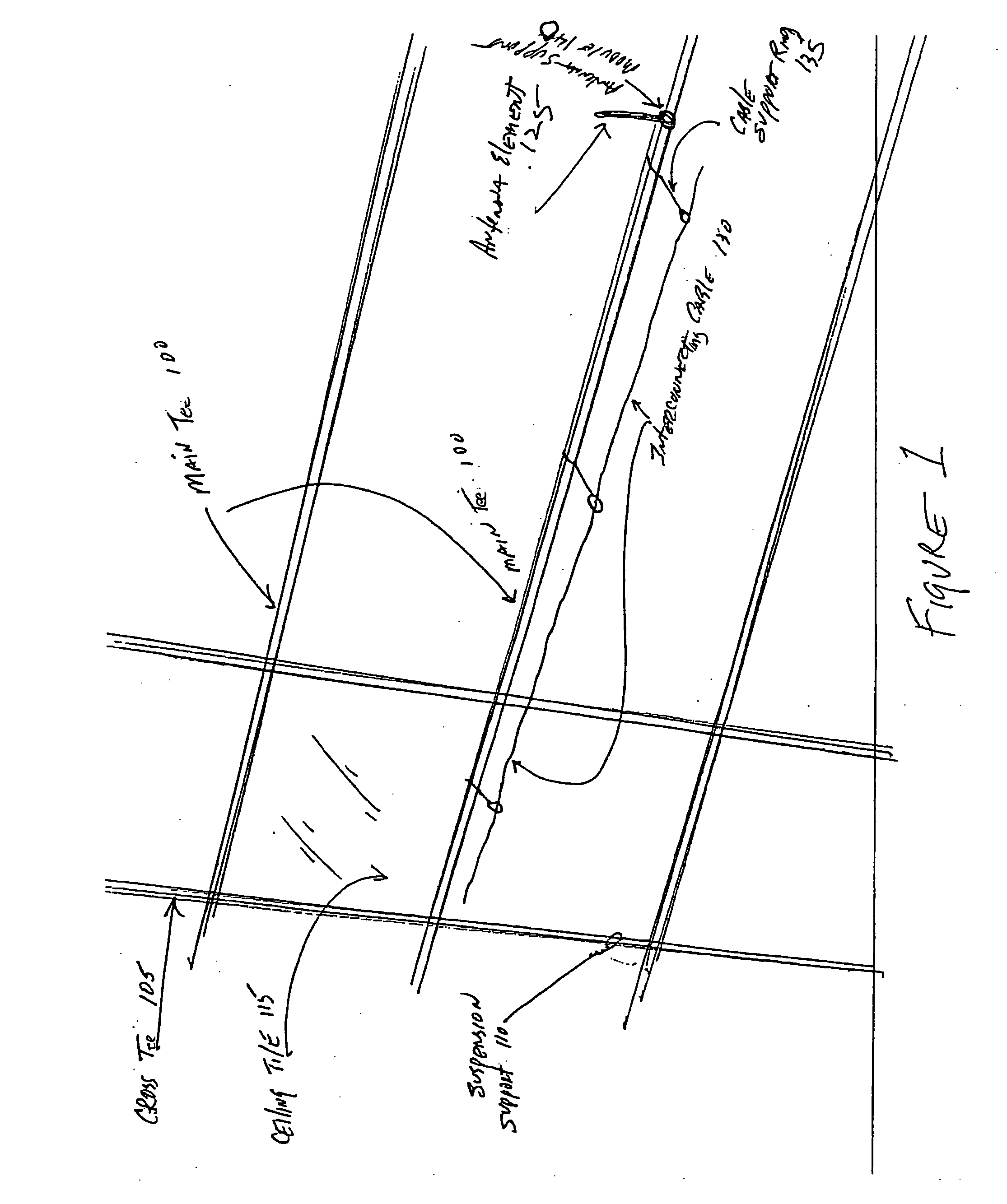
[0035]FIG. 1 depicts an antenna distribution system according to the first embodiment of the invention. Specifically, as shown in FIG. 1, the antenna distribution system is used in conjunction with a standard drop ceiling. The drop ceiling includes a main beam or tee 100 (hereinafter “main tee”), a plurality of cross beams or tees 105 (hereinafter “cross tees”), a plurality of suspension supports 110 for the main tee 100, and ceiling tiles 115. The main tee 100 and plurality of cross tees are attached to a ceiling grid 120. The main tee 100 and the plurality of cross tees 105 can be of any type of support grids such as a tee grid. As shown in FIGS. 1-9, the ceiling grid is a Fine Line Grid, however, an Exposed Tee Grid, Concealed Tee Grid, or a Slot Tee Grid can be used.

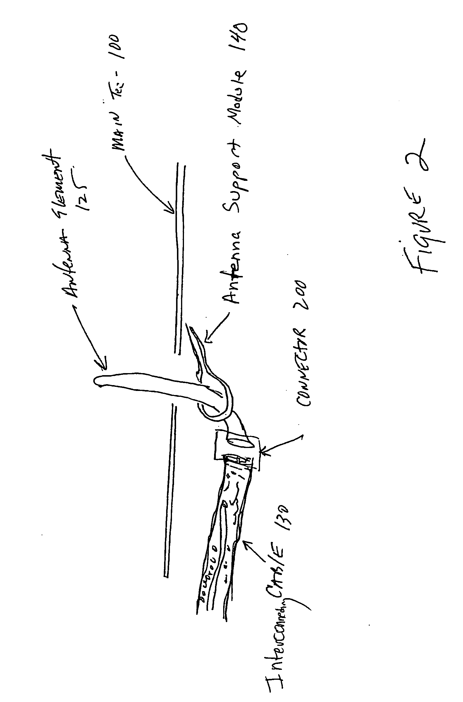
[0036] In the antenna distribution system, according to the first embodiment, an antenna element 125 is attached to the main tee 100. The antenna element 125 can be any device that is capable of radiating or detecti...


PUM


Abstract

An antenna distribution system used to facilitate transmission and reception of wireless communications within demised premises (indoors). The antenna distribution system includes a ceiling grid having an antenna element formed integral with or attached to the ceiling grid. The antenna is operably coupled to a wireless communications network. The antenna(s) are connected to one or more transceivers. The antenna can transmit and receive any type of wireless signal.

Description

FIELD OF INVENTION [0001] This invention relates to an antenna distribution system that is used to facilitate transmission and reception for wireless communications. More particularly, the invention relates to an antenna means attached to or formed integrally with a ceiling grid where the ceiling grid acts as a structural element to support and route the antenna means. BACKGROUND [0002] Indoor high-speed wireless communications have become widely used for both voice and data applications in many different types of organizations such as universities, hospitals, government agencies, emergency services and corporations. [0003] A typical wireless communications system includes a plurality of wireless base stations, wireless terminal devices, and antennas. The wireless terminal devices communicate with the wireless base stations. [0004] The wireless base stations are arranged to cover a plurality of areas within demised premises (indoor space). They are typically deployed in an elevated ...

Claims


Application Information

Patent Timeline
IPC IPC(8): H04M1/00
CPCH01Q13/203H01Q1/007
Inventor BRITE, PAULBRITE, JEFFREY
Owner PJB TECH
Why Eureka
Try Eureka