Ankle stirrup brace

a stirrup brace and ankle technology, applied in the field of ankle braces, can solve the problems of circumferential support, edema or swelling around the ankle and forefoot, and current ankle braces that do not effectively maximize edema release, and achieve the effect of greater suppor

Inactive Publication Date: 2007-03-01
RESTORATIVE CARE OF AMERICA
View PDF25 Cites 7 Cited by
  • Summary
  • Abstract
  • Description
  • Claims
  • Application Information

AI Technical Summary

Problems solved by technology

Some ankle injuries result in edema, or swelling around the ankle and forefoot.
Current ankle braces do not effectively maximize edema release, provide circumferential support, or are sufficiently adjustable to provide for a full range of motion for both planter and dorsi-flexion.

Method used


Image

  • Ankle stirrup brace
  • Ankle stirrup brace
  • Ankle stirrup brace

Examples


Embodiment Construction

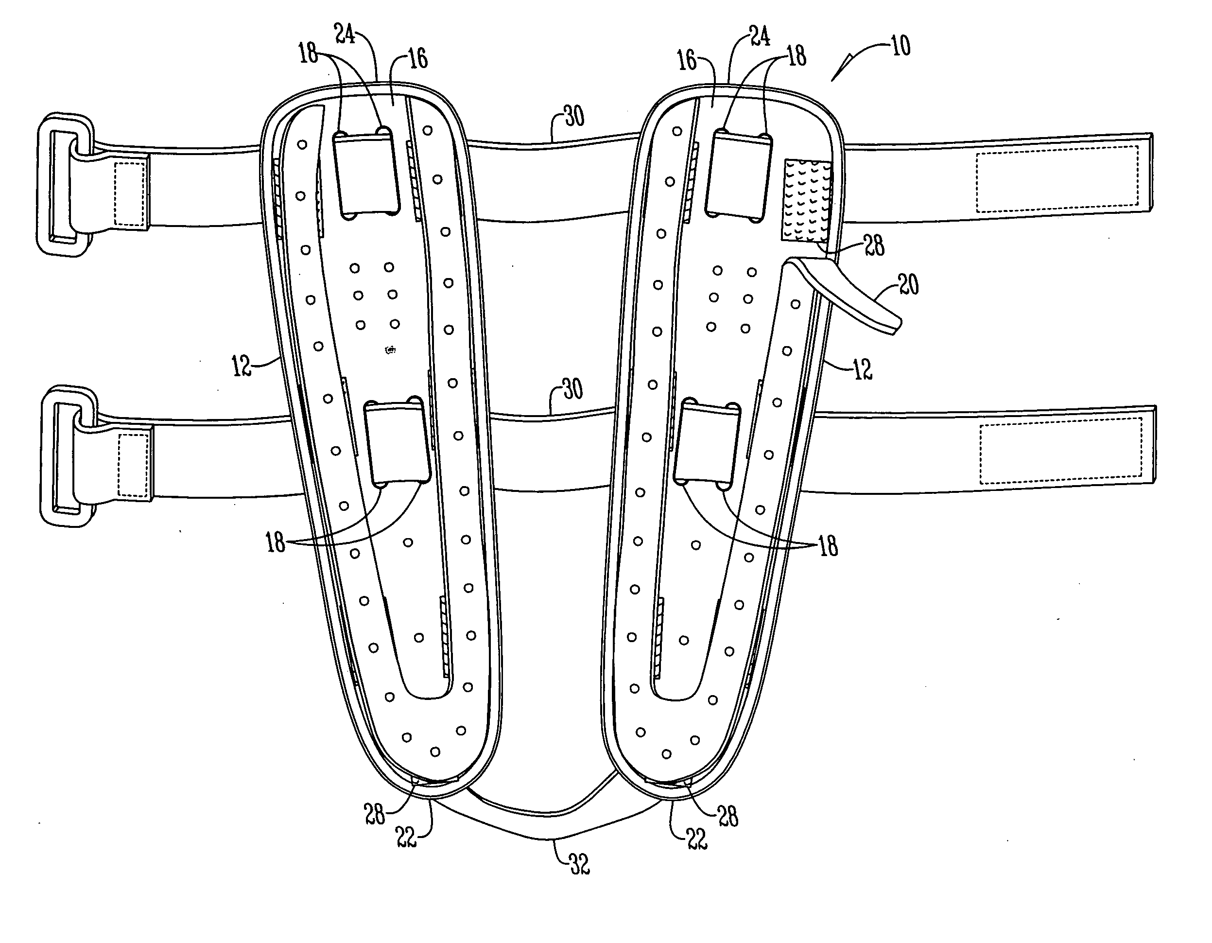
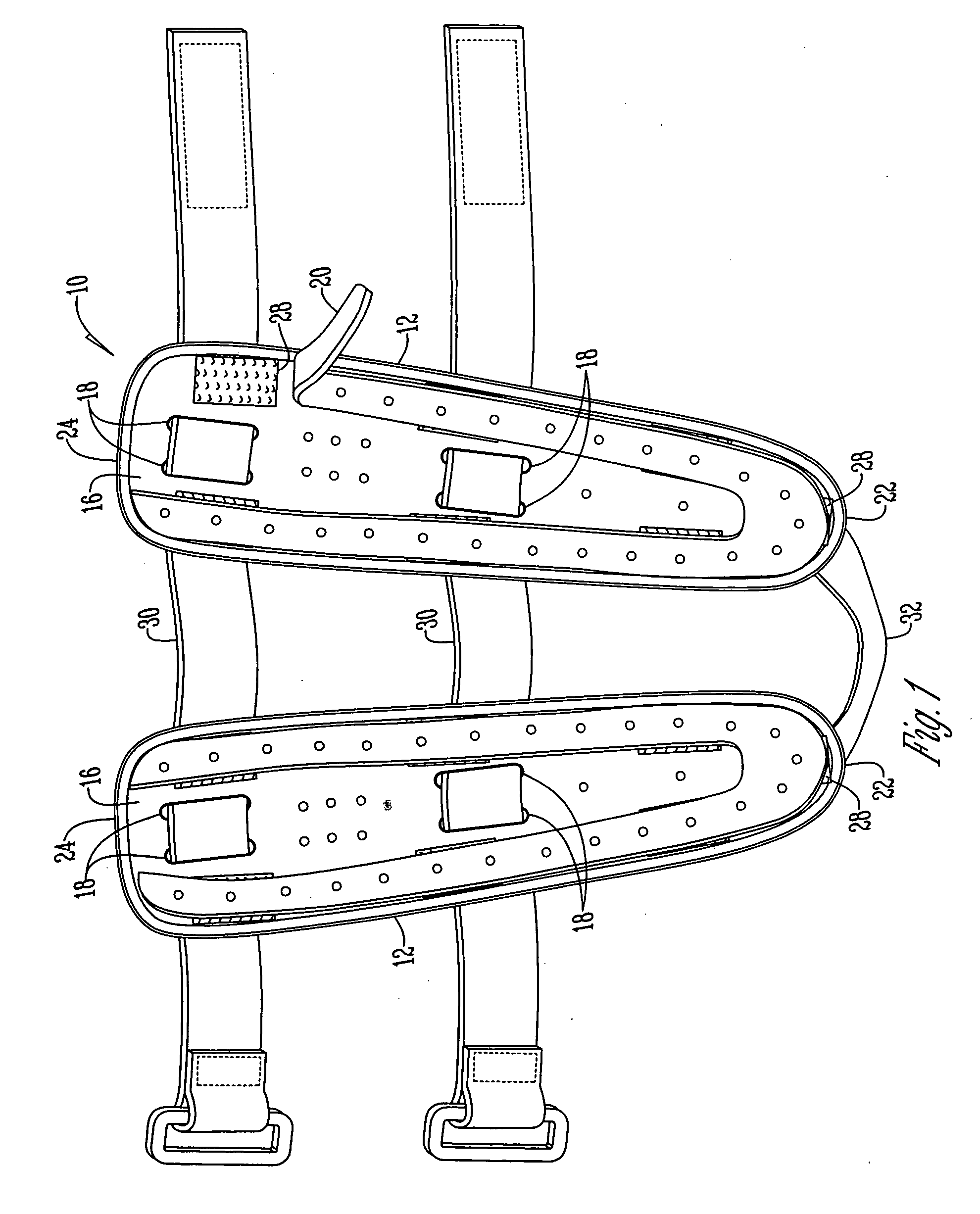
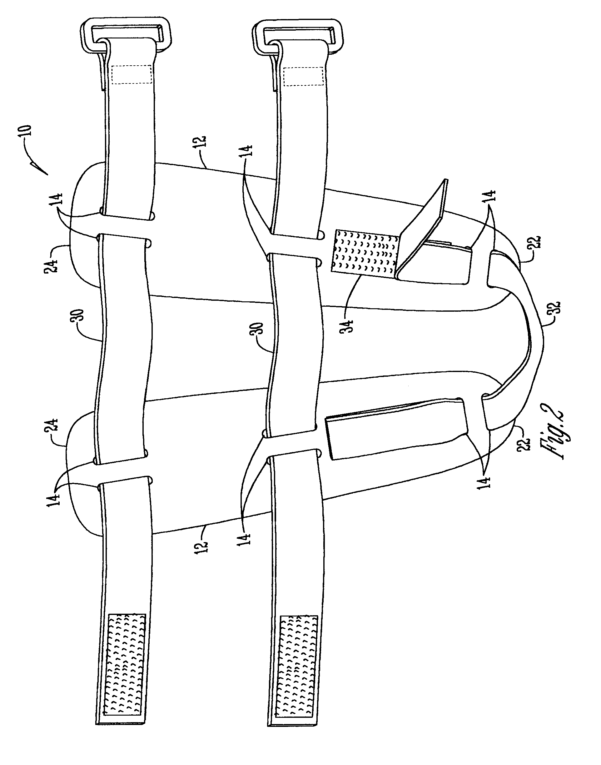
[0012] Referring to the Figures, an ankle brace 10 has a pair of shells 12 formed to fit the medial and lateral malleous portions of an individual's leg. The shells 12 are preferably made of either poly-propropulene or poly-ethylene or similar thermoplastic to provide either a firm or flexible fit as desired.

[0013] The shells 12 have a plurality of slots 14 that extend through the shells 12. Attached to the inner surface of the shells 12 are pads 16. The pads 16 have a plurality of openings 18 that are aligned with the slots 14 in the shells 12. Removably attached to the outer perimeter of the pads 16 are U-shaped / horseshoe strips 20 that are positioned to cup the medial and lateral malleous portions of an ankle. The strips 20 extend from the tip 22 of the shell 12 and pad 16 to the opposite end 24 and are preferably perforated and made of neoprene or closed cell foam. The strip 20 is positioned to aid in edema release and by extending the strip 20 from end 24 to the tip 22 edema r...


PUM


Abstract

An ankle brace having a pair of shells with a pad attached to the inner surface of the shells. Attached to the pads is a U-shaped strip positioned to cup the medial and lateral malleous portions of an ankle and extending from the tip of the shell to the opposite end of the shell. At least one strap is connected to the shells and extends around the shell, and an ankle strap is adjustably connected to the shells.

Description

BACKGROUND OF THE INVENTION [0001] This invention is directed to an ankle brace and more specifically, an ankle brace designed to maximize edema release. [0002] Ankle braces are well-known in the art. Generally, these braces are designed for application in the orthopedic medical field, where ankle sprains or factures are often supported and immobilized with a splint or brace so that a patient can continue to walk while the injury heals. Some ankle injuries result in edema, or swelling around the ankle and forefoot. [0003] Current ankle braces do not effectively maximize edema release, provide circumferential support, or are sufficiently adjustable to provide for a full range of motion for both planter and dorsi-flexion. Accordingly, there is a need for an ankle brace that addresses these problems. [0004] Therefore, an objective of this invention is to provide an ankle brace that maximizes edema release. [0005] Another objective of the invention is to provide an ankle brace that is e...

Claims


Application Information

Patent Timeline
Patent Type & Authority Applications(United States)
IPC IPC(8): A61F5/00
CPCA61F5/0111A61F2005/0174A61F5/30
Inventor MATTEAR, BRADLEY D.
Owner RESTORATIVE CARE OF AMERICA
Why Eureka
Try Eureka