Snap hook

US20070050957A1Inactive Publication Date: 2007-03-08PENSAFE

Image

  • Snap hook
  • Snap hook
  • Snap hook

Examples


Embodiment Construction

[0021] The present invention may be embodied in a number of different forms. However, the specification and drawings that follow describe and disclose only some of the specific forms of the invention and are not intended to limit the scope of the invention as defined in the claims that follow herein.

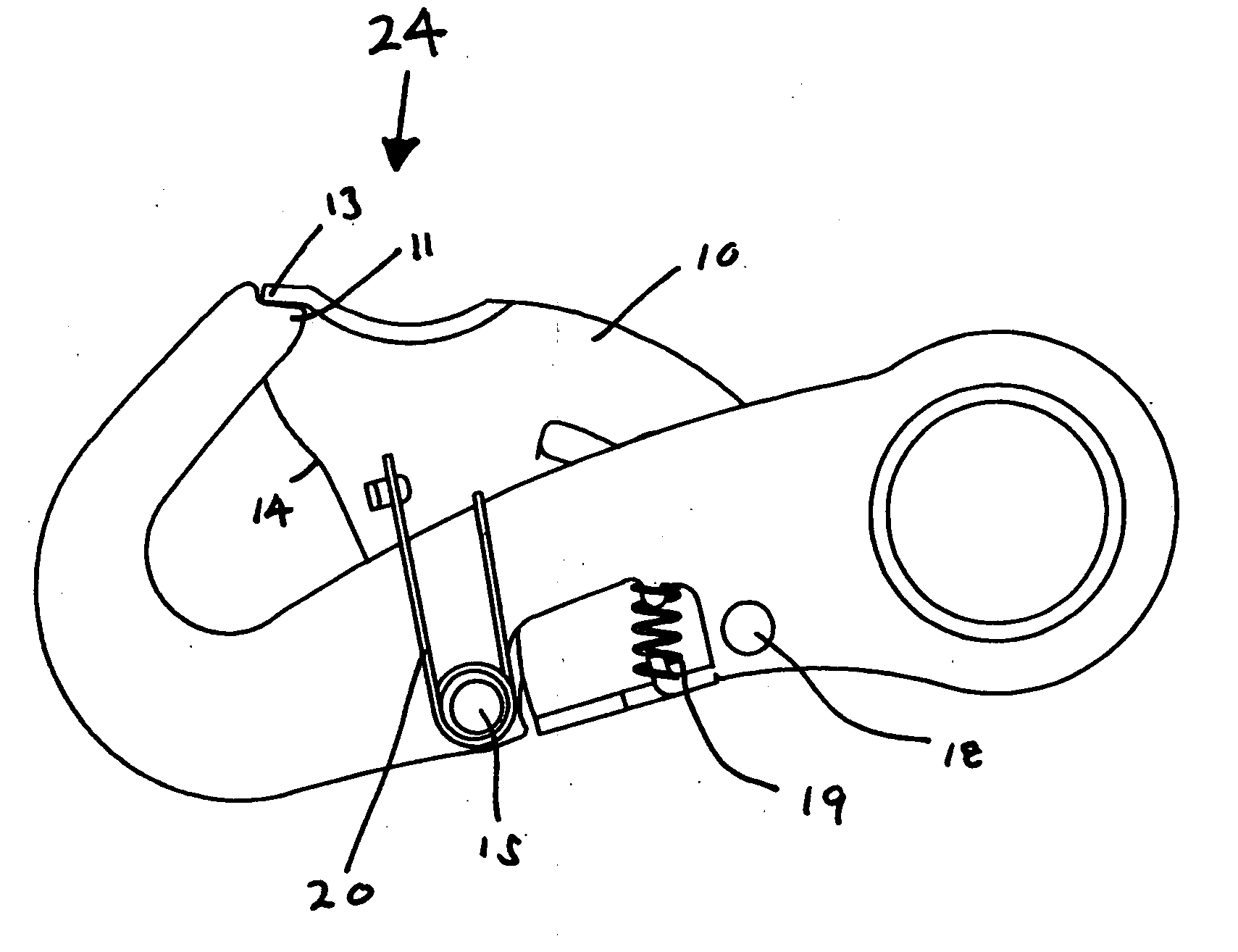
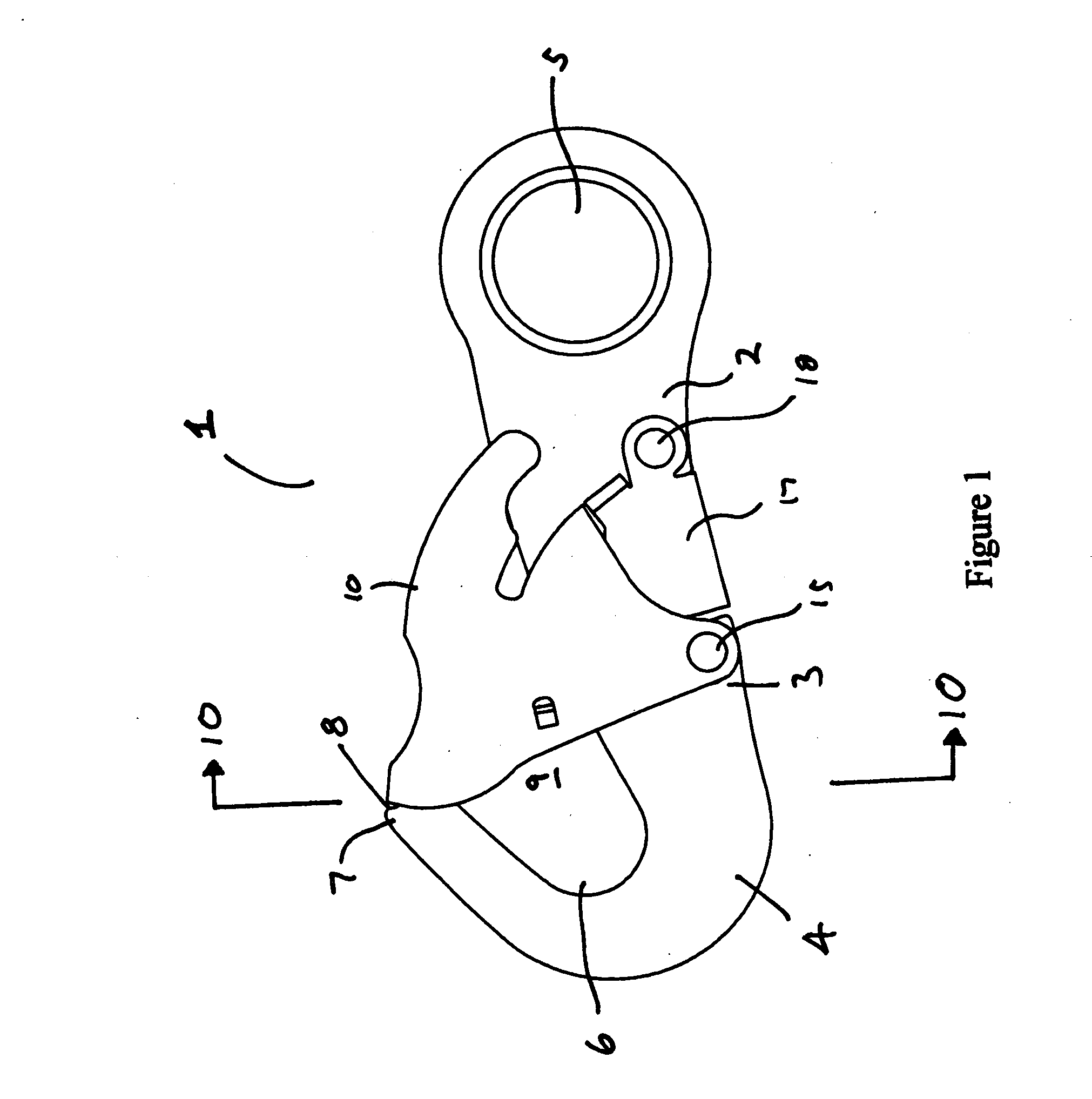
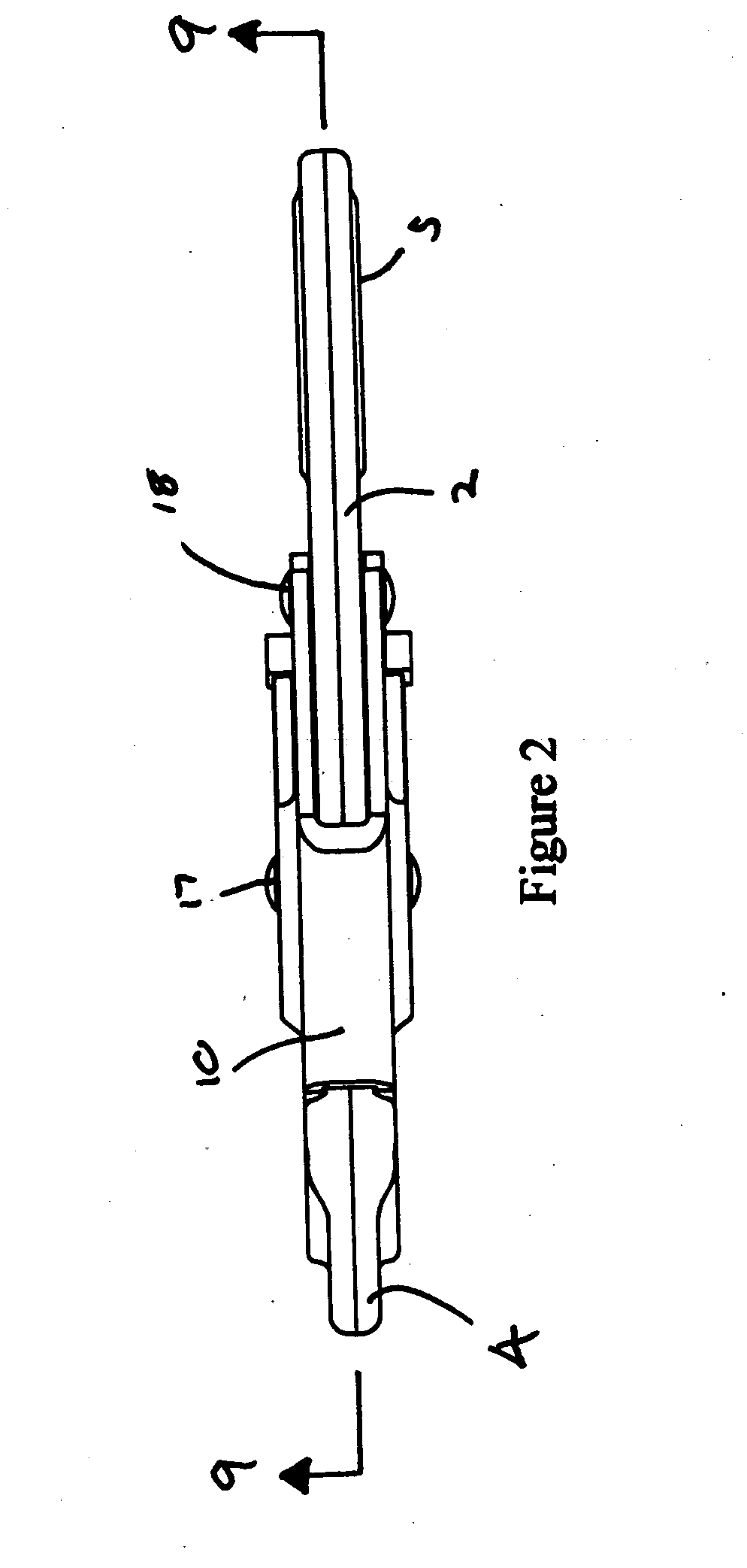
[0022] A snap hook constructed in accordance with one of the preferred embodiments of the present invention is shown in the attached drawings and represented by reference numeral 1. Snap hook 1 includes a hook shank 2 that is in the form of a main body 3 having a hook member 4 position generally at one of its ends. The opposite end of main body 3 is typically formed with an eye 5 or with a clevis or other means to secure the hook to a rope, cable, belt, chain or other object. In most instances main body 3, hook member 4 and eye 5 will be of unitary construction and formed from a high strength alloy steel or other metal. The structure may also be forged to further increase strength.

[002...


PUM


Abstract

A snap hook having a hook shank and a gate keeper. The hook shank includes a main body and a hook member that has a hook bowl and a hook bill. The hook bill and the main body define a gateway opening therebetween. The gate keeper has an outer face and has an open position and a closed position. The hook bill ends in a spigot and the gate keeper further includes a generally correspondingly dimensioned receiver such that when the gate keeper is in its closed position the spigot is at least partially received within the receiver, with the spigot and receiver thereby resisting movement of the gate keeper when a force directed in a generally inward direction toward the main body is applied to the outer face of the gate keeper.

Description

FIELD OF THE INVENTION [0001] This invention relates to snap hooks of the type that may be used on safety belts, safety harnesses, safety lines or any of a wide variety of other applications. In one particular embodiment, the invention relates to a snap hook having a new and improved gate keeper and hook bill design that enhances the ability of the gate keeper to withstand loading in multiple directions. BACKGROUND OF THE INVENTION [0002] Snap hooks in the safety and lifting industries take a variety of different forms and have an equally wide number of different applications. One application for snap hooks is in fall arrest systems. [0003] Safety and the prevention of falls is of primary importance for individuals working at heights, around areas of excavation, or where a fall could result in serious injury or death. In such cases the employment of a safety system to prevent falls is often not only desirable but a statutory requirement. Typically, safety systems that are commonly u...

Claims


Application Information

Patent Timeline
08 Mar 2007
Publication
US20070050957A1
IPC
F16B45/02
CPC
Y10T24/4534; F16B45/02; F16B45/026; F16B45/027
Inventors
BROWN, KEVIN