Vertical take-off and landing multirotor aircraft with at least eight thrust producing units
Active Publication Date: 2020-05-28
AIRBUS HELICOPTERS DEUT GMBH
0 Cites 10 Cited by
AI-Extracted Technical Summary
Problems solved by technology
However, in particular for recently appearing VTOL multirotor aircraft concepts related to fast flying and/or passenger carrying VTOL multirotor aircrafts, such an inclining of the entire VTOL multirotor aircraft implies multiple technical problems and disadvantages, such as e.g. a comparatively great power consumption, disproportional performance limitations, limited passenger comfort, and so on.
However, the provision of tiltable thrust producing units results in high system complexity and system weight due to a need of controlling and surveillance of required active actuation means.
Already the provision of such required active actuation means usually significantly increases an underlying system complexity and weight, so that respective maintenance costs of such VTOL multirotor aircrafts in convertible design are generally very high.
Furthermore, VTOL multirotor aircrafts in convertible design are usually designed for a specific flight condition, i.e. eit...
Benefits of technology
[0069]In other words, the present invention principally relates to a multiple thrust configuration with rotors/propellers that define rotor/propeller planes, which can be selected to be positioned atop of each other individually, a partial or full shrouding for enclosing any rotating parts of at most one of the rotors/propellers, preferably at least one electrical engine which drives each rotor/propell...
Abstract
A vertical take-off and landing multirotor aircraft with an airframe and at least eight thrust producing units, each one of the at least eight thrust producing units being provided for producing thrust in an associated predetermined thrust direction, wherein at least four thrust producing units of the at least eight thrust producing units form a first thrust producing units sub-assembly, and at least four other thrust producing units of the at least eight thrust producing units form a second thrust producing units sub-assembly, the first thrust producing units sub-assembly being operable independent of the second thrust producing units sub-assembly.
Application Domain
PropellersAircraft stabilisation +6
Technology Topic
AirplaneStructural engineering +4
Image
Examples
- Experimental program(1)
Example
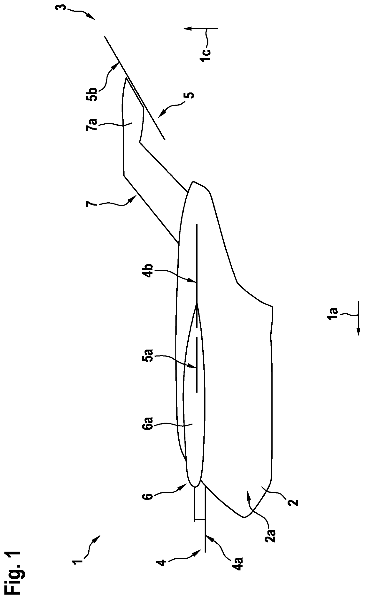
[0081]FIG. 1 shows an exemplary VTOL multirotor aircraft 1 with an aircraft airframe 2. The aircraft airframe 2 defines a supporting structure that is also referred to hereinafter as the “fuselage” of the VTOL multirotor aircraft 1.
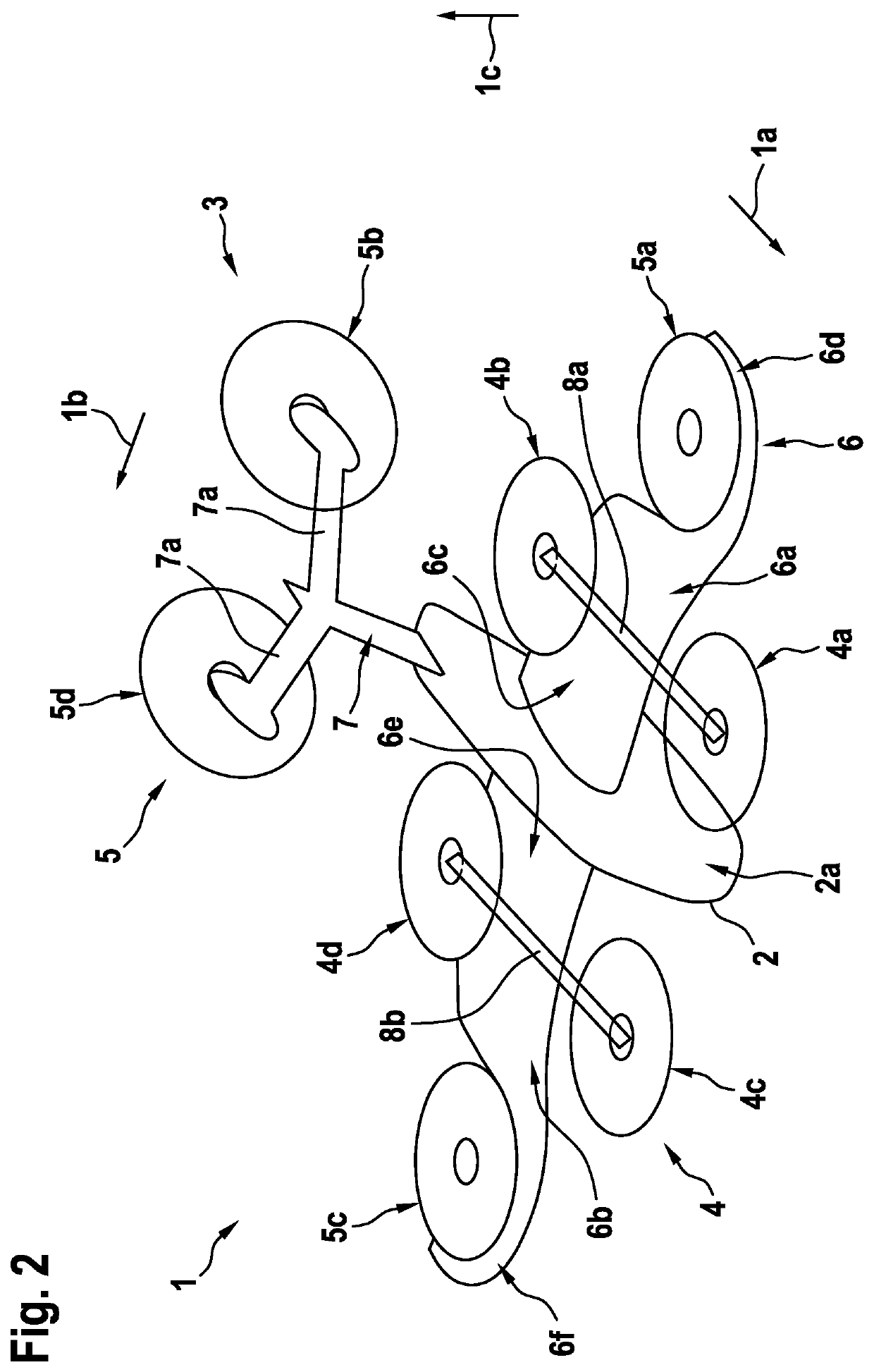
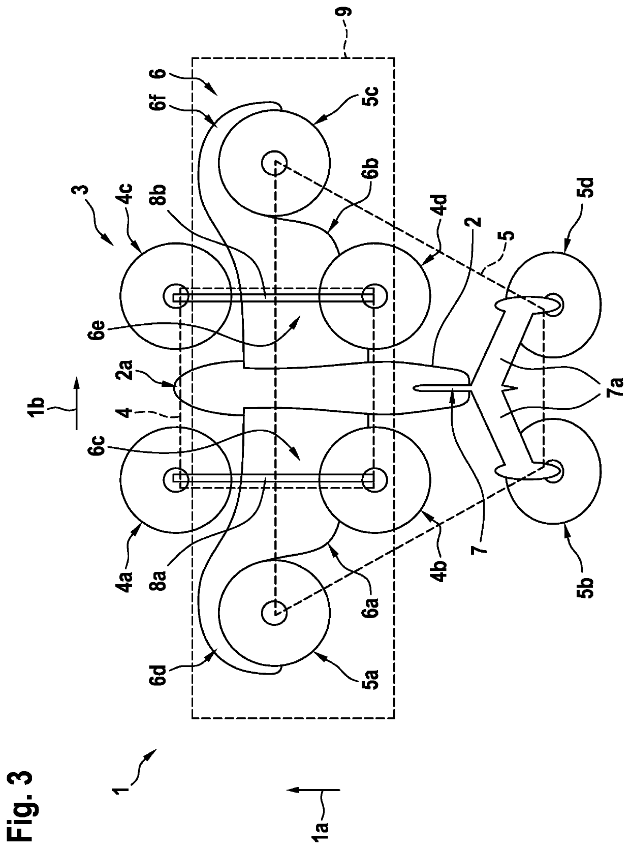
[0082]The fuselage 2 has an extension in longitudinal direction, which is illustratively represented by an arrow 1a that also exemplary indicates a forward flight direction of the VTOL multirotor aircraft 1, an extension in lateral direction (1b in FIG. 2, FIG. 3, FIG. 5, FIG. 6, FIG. 9 and FIG. 10), and an extension in vertical direction, which is illustratively represented by an arrow 1c that also exemplary indicates a vertical take-off direction. The fuselage 2 may be connected to any suitable undercarriage, such as e.g. a skid- or wheel-type landing gear.
[0083]Preferably, the fuselage 2 defines an internal volume 2a that is at least adapted for transportation of passengers, so that the VTOL multirotor aircraft 1 as a whole is adapted for transportation of passengers. The internal volume 2a is preferably further or alternatively adapted for accommodating operational and electrical equipment, such as e.g. an energy storage system that is required for operation of the VTOL multirotor aircraft 1.
[0084]It should be noted that exemplary configurations of the internal volume 2a that are suitable for transportation of passengers, but also or alternatively for accommodation of operational and electrical equipment, are readily available to the person skilled in the art and generally implemented to comply e.g. with applicable authority regulations and certification requirements regarding passenger transportation. Thus, as these configurations of the internal volume2a as such are not part of the present invention, they are not described in detail for brevity and conciseness.
[0085]Illustratively, the VTOL multirotor aircraft 1 comprises a plurality of thrust producing units 3. Preferably, each one of the plurality of thrust producing units 3 is provided for producing thrust in an associated predetermined thrust direction.
[0086]The plurality of thrust producing units 3 is preferably divided into a first thrust producing units sub-assembly 4 and a second thrust producing units sub-assembly 5. By way of example, the first thrust producing units sub-assembly 4 illustratively comprises thrust producing units 4a, 4b, and the second thrust producing units sub-assembly 5 illustratively comprises thrust producing units 5a, 5b. Configuration and structure of the first thrust producing units sub-assembly 4 and the second thrust producing units sub-assembly 5 are further explained below with reference to FIG. 2.
[0087]According to one aspect, the VTOL multirotor aircraft 1 comprises a wing 6. The wing 6 exemplary comprises a star board side half wing 6a and a board side half wing (6b in FIG. 2, FIG. 3, FIG. 5, FIG. 6, FIG. 9 and FIG. 10).
[0088]Furthermore, the VTOL multirotor aircraft 1 preferably comprises a rear stabilizer 7. The rear stabilizer 7 preferentially comprises a support structure 7a, which is by way of example illustratively connected to the thrust producing unit 5b of the second thrust producing units sub-assembly 5.
[0089]FIG. 2 shows the VTOL multirotor aircraft 1 of FIG. 1 with the fuselage 2 that extends in the longitudinal direction 1a, the vertical direction 1c, and a lateral direction that is illustratively represented by an arrow 1b. The VTOL multirotor aircraft 1 comprises the plurality of thrust producing units 3 of FIG. 1 with the first thrust producing units sub-assembly 4 and the second thrust producing units sub-assembly 5. Furthermore, the VTOL multirotor aircraft 1 comprises the wing 6 of FIG. 1 with the star board side half wing 6a and a board side half wing 6b, as well as the rear stabilizer 7 of FIG. 1.
[0090]By way of example, the plurality of thrust producing units 3 comprises eight thrust producing units, i.e. the thrust producing units 4a, 4b, 5a, 5b of FIG. 1, as well as thrust producing units 4c, 4d, 5c, 5d. Each one of these eight thrust producing units 4a, 4b, 4c, 4d, 5a, 5b, 5c, 5d is provided for producing thrust in an associated predetermined thrust direction. Preferably, at least 50% of the eight thrust producing units 4a, 4b, 4c, 4d, 5a, 5b, 5c, 5d is driven electrically.
[0091]The thrust producing units 4a, 4b, 4c, 4d illustratively form the first thrust producing units sub-assembly 4 and the thrust producing units 5a, 5b, 5c, 5d illustratively form the second thrust producing units sub-assembly 5. In other words, the first thrust producing units sub-assembly 4 exemplary comprises four thrust producing units and the second thrust producing units sub-assembly 5 also exemplary comprises four thrust producing units. Preferably, the first thrust producing units sub-assembly 4 is operable independent of the second thrust producing units sub-assembly 5.
[0092]According to one aspect, the thrust producing units 4a, 4b, 4c, 4d of the first thrust producing units sub-assembly 4 are driven electrically, while the thrust producing units 5a, 5b, 5c, 5d of the second thrust producing units sub-assembly 5 are driven with different power units, such as e.g. combustion and/or turbine engines. Alternatively, the thrust producing units 5a, 5b, 5c, 5d of the second thrust producing units sub-assembly 5 may be driven electrically, while the thrust producing units 4a, 4b, 4c, 4d of the first thrust producing units sub-assembly 4 are driven with different power units, such as e.g. combustion and/or turbine engines. Still alternatively, selected thrust producing units from the first and second thrust producing units sub-assemblies 4, 5 may be driven electrically, e.g. the thrust producing units 4b, 4d, 5a, 5c, while the remaining thrust producing units from the first and second thrust producing units sub-assemblies 4, 5, i.e. the thrust producing units 4a, 4c, 5b, 5d, are driven with different power units, such as e.g. combustion and/or turbine engines.
[0093]Preferably, the first thrust, producing units sub-assembly 4 is dedicated to control of vertical taking-off and landing. The second thrust producing units sub-assembly 5 is preferably dedicated to control of low-speed cruise operation.
[0094]According to one aspect, the thrust producing units 5b, 5d of the second thrust producing units sub-assembly 5 are inclined by a predetermined inclination angle (β in FIG. 4) with respect to the longitudinal direction la of the VTOL multirotor aircraft 1. They are preferably non-tiltably connected to the fuselage 2 for generating forward thrust at least during low-speed cruise operation. More specifically, the thrust producing units 5b, 5d are exemplary rigidly mounted to the support structure 7a of the rear stabilizer 7.
[0095]The thrust producing units 4a, 4c of the first thrust producing units sub-assembly 4.in turn are preferably tiltably connected to the fuselage 2 for generating additional forward thrust at least during high-speed cruise operation. However, it should be noted that tiltably connecting thrust producing units to the fuselage of a VTOL multirotor aircraft is well-known in the art and as such not the object of the present invention. Therefore, the tiltable connection of the thrust producing units 4a, 4c to the fuselage 2 is not described in more detail.
[0096]Preferably, high-speed cruise operation comprises operation at a velocity of at least 0.7*Vh, while low-speed operation comprises operation of the VTOL multirotor aircraft 1 at a velocity of 0.3*Vh to less than 0.7*Vh. Vh is a predefined cruise speed of the VTOL multirotor aircraft 1, which may be aircraft-resp. application-dependent.
[0097]Illustratively, the thrust producing units 4b, 4d of the first thrust producing units sufe-assembly 4 and the thrust producing units 5a, 5c of the second thrust producing units sub-assembly 5 are connected to the wing 6. More specifically, the star board side half wing 6a preferably accommodates at least partly the thrust producing units 4b, 5a, while the board side half wing 6b preferably accommodates at least partly the thrust producing units 4d, 5c.
[0098]By way of example, the thrust producing unit 4b is arranged at an inboard section 6c of the star board side half wing 6a and the thrust producing unit 5a is arranged at an outboard section 6d of the star board side half wing 6a. Likewise, the thrust producing unit 4d is illustratively arranged at an inboard section 6e of the board side half wing 6b and the thrust producing unit 5c is illustratively arranged at an outboard section 6f of the board side half wing 6b.
[0099]Preferably, the thrust, producing units 4a, 4c of the first thrust producing units sub-assembly 4, which are tiltably connected to the fuselage 2 for generating additional forward thrust at least during high-speed cruise operation, are arranged in the longitudinal direction la of the VTOL multirotor aircraft 1 upstream of the wing 6. More generally, preferably at least 25% of the eight thrust producing units 4a, 4b, 4c, 4d, 5a, 5b, 5c, 5d are arranged in the longitudinal direction la of the VTOL multirotor aircraft 1 upstream of the wing 6. In the illustrated example, only two of the eight thrust producing units are arranged in the longitudinal direction la upstream of the wing 6, i.e. exactly 25% of the eight thrust producing units 4a, 4b, 4c, 4d, 5a, 5b, 5c, 5d.
[0100]However, in order to avoid undesired parasitical interactions between all thrust producing units that are arranged in the longitudinal direction la of the VTOL multirotor aircraft i upstream of the wing 6, a respective number of thrust producing units that are arranged in the longitudinal direction la of the VTOL multirotor aircraft 1 upstream of the wing 6 is preferably restricted. Accordingly, advantageously not more than 40% of all thrust producing units, in the present example of the thrust producing units 4a, 4b, 4c, 4d, 5a, 5b, 5c, 5d, should be arranged in the longitudinal direction la of the VTOL multirotor aircraft 1 upstream of the wing 6.
[0101]According to one aspect, the thrust producing units 4a, 4b are interconnected by means of an associated interconnection beam 8a. Likewise, the thrust producing units 4c, 4d are preferably interconnected by an associated interconnection beam 8b. The interconnection beams 8a, 8b may comprise suitable drive shafts that drivingly interconnect the respective thrust producing units 4a, 4b, 4c, 4d. Alternatively, each one of the respective thrust producing units 4a, 4b, 4c, 4d may be driven by a respectively attributed electrical engine.
[0102]FIG. 3 shows the VTOL multirotor aircraft 1 of FIG. 2 with the plurality of thrust producing units 3 that comprises the first and second thrust producing units sub-assemblies 4, 5, the wing 6, and the rear stabilizer 7. Similar to FIG. 1 and FIG. 2, the VTOL multirotor aircraft 1 is illustrated in an operation mode that corresponds to vertical taking-off and landing.
[0103]According to one aspect, the thrust producing units 4b, 4d of the first thrust producing units sub-assembly 4 and the thrust producing units 5a, 5c of the second thrust producing units sub-assembly 5 are arranged in an intersection zone 9 of the first and second thrust producing units sub-assemblies 4, 5. The thrust producing units 4b, 4d, 5a, 5c in the intersection zone 9 are preferentially non-tiltably connected to the fuselage 2 for generating lift at least during vertical taking-off and landing.
[0104]Preferably, at least 25% of the eight thrust producing units 4a, 4b, 4c, 4d, 5a, 5b, 5c, 5d are arranged in the intersection zone 9 and, preferentially, in the wing 6. In the illustrated example, four of the eight thrust producing units, i.e. the thrust producing units 4b, 4d, 5a, 5c, are arranged in the intersection zone 9 resp. in the wing 6, i.e. exactly 50% of the eight, thrust producing units 4a, 4b, 4c, 4d, 5a, 5b, 5c, 5d.
[0105]Illustratively, the intersection zone 9 is provided with the wing 6. The wing 6 in the intersection zone 9 preferably accommodates at least partly each one of the thrust producing units 4b, 4a, 5a, 5c which are arranged in the intersection zone 9.
[0106]In an exemplary operation of the VTOL multirotor aircraft 1, the first and second thrust producing units sub-assemblies 4, 5 are operational during vertical taking-off to provide lift. However, a respective thrust balance between the first and second thrust producing units sub-assemblies 4, 5 is preferably controlled such that essentially the first thrust producing units sub-assembly 4 provides the lift. In other words, the lift provided by the second thrust producing units sub-assembly 5 would be significantly smaller than the lift provided by the first thrust producing units sub-assembly 4. In order to switch from vertical taking-off to cruise operation, the respective thrust balance is switched from the first thrust producing units sub-assembly 4 to the second thrust producing units sub-assembly 5. Thus, the VTOL multirotor aircraft 1 can at least initially be controlled in the longitudinal direction 1a due to the (pre-)inclined thrust producing units 5b, 5d of the second thrust producing units sub-assembly 5. More specifically, during low-speed operation of the VTOL multirotor aircraft 1 no additional propulsion for forward flight by the thrust producing units 4a, 4c of the first thrust producing units sub-assembly 4 is required. If, however, transition to high-speed operation is required, an in-flight transformation of the first thrust producing units sub-assembly 4 by means of a respective inclination, i.e. an active tilting of the thrust producing units4a, 4c is performed.
[0107]Alternatively, the first thrust producing units sub-assembly 4 may be operational to provide lift during vertical taking-off, while the second thrust producing units sub-assembly 5 may be in an Off-mode during vertical taking-off. Then, in order to switch from vertical taking-off to cruise operation, the second thrust producing units sub-assembly 5 may be activated such that the thrust producing units 5b, 5d generate forward thrust, while the thrust producing units 5a, 5c of the second thrust producing units sub-assembly 5 may provide sufficient lift in cruise operation. Thus, after having performed a respective in-flight transformation of the VTOL multirotor aircraft 1 from vertical taking-off to cruise operation, the first thrust producing units sub-assembly 4 may e.g. be completely turned off, e.g. if only low-speed cruise operation is required, or alternatively the thrust producing units 4a, 4c of the first thrust producing units sub-assembly 4 may be tilted to generate additional forward thrust such that high-speed cruise operation is enabled. In this case, only the thrust producing units 4b, 4d of the first thrust producing units sub-assembly 4 may be turned off.
[0108]Still alternatively, if only low-speed cruise operation is required, the thrust producing units 5b, 5d of the second thrust producing units sub-assembly 5 may remain in Off-mode, and only the thrust producing units 5a, 5c are turned on during the in-flight transformation so that the thrust producing units 4b, 4d, 5a, 5c provide sufficient lift for the VTOL multirotor aircraft 1 such that the thrust, producing units 4a, 4c may be tilted during the in-flight transformation so as to generate the forward thrust that is required for low-speed cruise operation.
[0109]FIG. 4 shows the VTOL multirotor aircraft 1 of FIG. 1 to FIG. 3, which is now by way of example illustrated in an exemplary cruise operation. In correspondence to FIG. 1 to FIG. 3, the VTOL multirotor aircraft 1 comprises the fuselage 2, the plurality of thrust producing units 3 that comprises the first thrust producing units sub-assembly 4 and the second thrust producing units sub-assembly 5, the wing 6 and the rear stabilizer 7.
[0110]As described above with reference to FIG. 3, during cruise operation the thrust producing unit 4a (and the thrust producing unit 4c of FIG. 2 and FIG. 3) may be tilted by an associated inclination angle α with respect to the fuselage 2, i.e. with respect to a reference direction, such as horizontal direction 10. The horizontal direction 10 illustratively corresponds, i.e. is parallel, to the longitudinal direction 1a of the VTOL multirotor aircraft 1.
[0111]The associated inclination angle α preferably ranges in an interval from −90° to 0°, and illustratively amounts to −90°. Preferably, at least during high-speed cruise operation the associated inclination angle α amounts to −90°.
[0112]According to one aspect, the thrust producing unit 4a (and the thrust producing unit 4c of FIG. 2 and FIG. 3) of the first thrust producing units sub-assembly 4 may already be tilted during low-speed cruise operation, but is (are) preferably at least tilted during high-speed cruise operation for generating additional forward thrust, as described in more detail below with reference to FIG. 5.
[0113]FIG. 4 further illustrates an exemplary predetermined inclination angle β of the thrust producing unit 5b (and the thrust producing unit 5d of FIG. 2 and FIG. 3) of the second thrust producing units sub-assembly 5 with respect to the horizontal direction 10. Preferably, the predetermined inclination angle β ranges from −25° to −45°, and illustratively amounts to −30°.
[0114]FIG. 5 shows the VTOL multirotor aircraft 1 of FIG. 4 with the fuselage 2, the plurality of thrust producing units 3 that comprises the first and second thrust producing units sub-assemblies 4, 5, the wing 6 and the rear stabilizer 7. In accordance with FIG. 4, the VTOL multirotor aircraft 1 is again shown during cruise operation.
[0115]As explained above with reference to FIG. 4, in cruise operation and, more specifically, at least during high-speed cruise operation, the thrust producing unit 4a is inclined by the predetermined inclination angle α of FIG. 4, which in FIG. 4 and FIG. 5 illustratively amounts to −90°. Likewise, the thrust producing unit 4c of the first thrust producing units sub-assembly 4 is similarly inclined by the predetermined inclination angle α of FIG. 4. Thus, the thrust producing unit 4c is illustratively also inclined by an angle of −90°.
[0116]FIG. 6 shows the VTOL multirotor aircraft 1 of FIG. 4 and FIG. 5 during cruise operation, with the fuselage 2, the plurality of thrust producing units 3 that comprises the first and second thrust producing units sub-assemblies 4, 5, the wing 6 and the rear stabilizer 7. FIG. 6 further illustrates constitution of the first thrust producing units sub-assembly 4 that comprises the thrust producing units 4a, 4b, 4c, 4d, as well as of the second thrust producing units sub-assembly 5 that comprises the thrust producing units 5a, 5b, 5c, 5d.
[0117]Moreover, FIG. 6 further illustrates inclination of the tiltable thrust producing units 4a, 4c of the first thrust producing units sub-assembly 4, as well as of the thrust producing units 5b, 5d of the second thrust producing units sub-assembly 5, which are pre-inclined but non-tiltably arranged at the support structure 7a of the rear stabilizer 7. Finally, FIG. 6 again illustrates the intersection zone 9, wherein illustratively the wing 6 and the thrust producing units 4b, 4d of the first thrust producing units sub-assembly 4 and the thrust producing units 5a, 5c of the second thrust producing units sub-assembly 5 are arranged.
[0118]FIG. 7 shows the VTOL multirotor aircraft 1 in the configuration according to FIG. 3 during an in-flight transformation into the configuration according to FIG. 4, i.e. an in-flight transformation from a respectively exemplary taking-off and landing configuration according to FIG. 1 into a respective cruise operation configuration according to FIG. 4. As explained above with reference to FIG. 3, the in-flight transformation is performed by a suitable control of the first and second thrust producing units sub-assemblies 4, 5 of the VTOL multirotor aircraft 1 (cp. FIG. 3). One of the elements of the in-flight transformation consists, as explained above with respect to FIG. 4, in tilting of the thrust producing unit 4a (and the thrust producing unit 4c of FIG. 2, FIG. 3, FIG. 5, FIG. 6) of the first thrust producing units sub-assembly 4 by the predetermined inclination angle α of FIG. 4.
[0119]FIG. 8 shows an exemplary power-velocity-diagram 11 having an axis of abscissae 11a that represents the velocity and an axis of ordinate 11b that represents a respectively required power of the VTOL multirotor aircraft 1 of FIG. 1 to FIG. 7. By way of example, the power-velocity-diagram 11 illustrates a respective power that is required to obtain a desired velocity in three exemplary flight phases 12a, 12b, 12c.
[0120]The flight phase 12a represents an exemplary taking-off or landing of the VTOL multirotor aircraft 1 according to FIG. 1 to FIG. 3. The flight phase 12b represents an exemplary in-flight transformation of the VTOL multirotor aircraft 1 according to FIG. 7, i.e. the in-flight transformation from the taking-off and landing configuration according to FIG. 1 to FIG. 3 into an exemplary cruise operation configuration according to FIG. 4 to FIG. 6. The flight phase 12c exemplary illustrates cruise operation of the VTOL multirotor aircraft 1 according to FIG. 4 to FIG. 8.
[0121]By way of example, a range 13a is indicated, which illustrates a preferred resp. optimum cruise power range. In order not to descend below the optimum cruise power range 13a, in-flight transformation of the VTOL multirotor aircraft 1 is required. By way of example, the in-flight transformation is performed as described above with respect to FIG. 7 by means of the first thrust producing units sub-assembly 4 of the preceding figures starting at a first thrust producing system transformation range 13b.
[0122]Illustratively, the in-flight transformation of the VTOL multirotor aircraft X is finished at a point 13c, which illustrates a preferred resp. optimum cruise velocity of the VTOL multirotor aircraft 1.
[0123]It should be noted that modifications of the above described aspects of the present invention are also within the common knowledge of the person skilled in the art and, thus, also considered as being part of the present, invention. An example for such modifications is hereinafter described with reference to FIG. 9 and FIG. 10.
[0124]FIG. 9 shows the VTOL multirotor aircraft 1 of FIG. 1 to FIG. 3, which is illustratively in the exemplary taking-off and landing configuration according to FIG. 1 to FIG. 3. The VTOL multirotor aircraft 1 comprises the fuselage 2, the plurality of thrust producing units 3 that comprises the first and second thrust producing units sub-assemblies 4, 5, the wing 6 and the rear stabilizer 7 according to the above-described FIG. 1 to FIG. 3. However, in contrast thereto, the VTOL multirotor aircraft 1 now comprises two additional thrust producing units 14a, 14b. The additional thrust producing units 14a, 14b are exemplary inclined by approximately −90° with respect to the longitudinal, direction 1a, i.e. the horizontal direction 10 of FIG. 4. Preferably, the additional thrust producing units 14a, 14b are non-tiltably connected to the fuselage 2 for generating additional forward thrust at least during high-speed cruise operation.
[0125]According to one aspect, the additional thrust producing units 14a, 14b are respectively connected by means of associated interconnection beams 8c, 8d to the thrust producing units 5a, 5c of the second thrust producing units sub-assembly 5. As explained above with reference to the interconnection beams 8a, 8b in FIG. 2, the interconnection beams 8c, 8a may comprise respective drive shafts that drivingly interconnect the corresponding thrust producing units 14a, 5a as well as 14b, 5c. Accordingly, the additional thrust producing units 14a, 14b preferably form part of the second thrust producing units sub-assembly 5. However, each one of the thrust producing units 14a, 5a as well as 14b, 5c may also be driven individually, e.g. by means of one or more associated electrical engines.
[0126]It should be noted that the additional thrust producing units 14a, 14b are exemplary arranged in the longitudinal direction 1a of the VTOL multirotor aircraft 1 upstream of the wing 6. Thus, in the example of FIG. 9 the four thrust producing units 4a, 4c, 14a, 14b of the ten thrust producing units 4a, 4b, 4c, 4d, 5a, 5b, 5c, 5d, 14a, 14b are arranged in the longitudinal direction 1a upstream of the wing 6, i.e. exactly 40% of the ten thrust producing units 4a, 4b, 4c, 4d, 5a, 5b, 5c, 5a, 14a, 14b.
[0127]FIG. 10 shows the VTOL multirotor aircraft 1 of FIG. 9 with the fuselage 2, the plurality of thrust producing units 3 that comprises the first and second thrust producing units sub-assemblies 4, 5, the wing 6 and the rear stabilizer 7. FIG. 10 further illustrates the arrangement of the thrust producing units 4b, 4d, 5a, 5c in the interconnection zone 9, as described above with reference to FIG. 3. However, FIG. 10 further illustrates arrangement of the additional thrust producing units 14a, 14b of FIG. 9 in the intersection zone 9 as well.
[0128]As described above with reference to FIG. 1 to FIG. 7 as well as FIG. 9 and FIG. 10, the intersection zone 9 illustratively comprises the wing 6. However, it should be noted that use of the wing 6 is merely described by way of example and not for limiting the present application accordingly. Instead, e.g. a blown-wing, one or more partial shroudings and/or full shroudings may likewise be used with the VTOL multirotor aircraft 1.
[0129]In the illustrative configuration with the wing 6, preferably a partial shrouding 15a, 15b, 15c, 15d is provided for each one of the thrust producing units which are accommodated in the wing 6. Thus, aerodynamic drag can be reduced significantly.
[0130]Illustratively, the partial shrouding 15a is provided for the thrust producing unit 5a, the partial shrouding 15b is provided for the thrust producing unit 4b, the partial shrouding 15c is provided for the thrust producing unit 4d, and the partial shrouding 15d is provided for the thrust producing unit 5c. This likewise applies to all configurations of the VTOL multirotor aircraft 1 described above with reference to FIG. 1 to FIG. 7 as well as FIG. 9. Nevertheless, it should be noted that the partial shroudings 15a, 15b, 15c, 15d are also only described by way of example and not for limiting the present invention accordingly, as e.g. one or more of the partial shroudings 15a, 15b, 15c, 15d may e.g. be replaced by full shroudings.
[0131]It should be noted that suitable partial shroudings that may be used to implement; the partial shroudings 15a, 15b, 15c, 15d, as well as suitable full shroudings that may be used to implement respective full shroudings, are well-known by the person skilled in the art and are not the object of the present invention as such. By way of example, respective shroudings are described in co-pending European patent applications EP 17400008.3 and EP 18400003.2. It should be noted that the content of these two co-pending European patent applications is considered as being entirely incorporated by reference and, as such, as forming entirely part of the present description, so that a more detailed description of respective shroudings can be omitted for brevity and conciseness.
[0132]Furthermore, it should be noted that the partial shroudings 15a, 15b, 15c, 15d and/or respective full shroudings are preferably configured with longitudinally directed carrier beams, such as e.g. described in the co-pending European patent application 18400014.9. Again, the content; of this European patent application is considered as being entirely incorporated by reference and, as such, as forming entirely part of the present description, so that a more detailed description of such longitudinally oriented carrier beams can be omitted for brevity and conciseness.
[0133]Finally, it should be noted that with respect to FIG. 1 to FIG. 7, exactly eight thrust producing units are illustrated. Subsequently, with respect to FIG. 9 and FIG. 10, ten thrust producing units are illustrated. Thus, it should be clear that the inventive VTOL multirotor aircraft 1 preferably comprises at least eight thrust producing units, but may be provided with more than eight thrust producing units depending on an intended e.g. application-specific implementation. Accordingly, each one of the first and second thrust producing units sub-assemblies 4, 5 comprises at least four thrust producing units, but may comprise more than the four thrust producing units as illustrated in FIG. 9 and FIG. 10. Furthermore, preferably at least two thrust producing units of each one of the first and second thrust producing units sub-assemblies 4, 5 are arranged in the intersection zone 9, preferably at least two thrust producing units of the first thrust producing units sub-assembly 4 are arranged upstream of the wing 6, at least two thrust producing units of the second thrust producing units sub-assembly 5 are inclined fixedly by the predetermined inclination angle β, and at least two thrust producing units of the first thrust producing units sub-assembly 4 are tiltably connected to the airframe.
REFERENCE LIST
[0134]1 Vertical take-off and landing multirotor aircraft
[0135]1a Aircraft longitudinal resp. length direction and forward flight direction
[0136]1b Aircraft lateral resp. width direction
[0137]1c Aircraft vertical resp. height direction and vertical take-off direction
[0138]2 Aircraft airframe
[0139]2a Aircraft airframe internal volume
[0140]3 Thrust producing units
[0141]4 First thrust producing units sub-assembly
[0142]4a, 4b, 4c, 4d Thrust producing units of first thrust producing units sub-assembly
[0143]5 Second thrust producing units sub-assembly
[0144]5a, 5b, 5c, 5d Thrust producing units of second thrust producing units sub-assembly
[0145]6 Wing
[0146]6a Star board side half wing
[0147]6b Board side half wing
[0148]6c Star board side half wing inboard section
[0149]6d Star board side half wing outboard section
[0150]6e Board side half wing inboard section
[0151]6f Board side half wing outboard section
[0152]7 Rear stabilizer
[0153]7a Thrust producing unit support structure
[0154]8a, 8b, 8c, 8d Thrust producing unit interconnection beams
[0155]9 Intersection zone
[0156]10 Horizontal orientation
[0157]11 Power-velocity-diagram
[0158]11a Axis of abscissae representing velocity
[0159]11b Axis of ordinate representing power
[0160]12a, 12b, 12c Flight phases
[0161]13a Optimum cruise power range
[0162]13b First thrust producing system transformation range
[0163]13c Optimum cruise velocity
[0164]14a, 14b Additional thrust producing units
[0165]15a, 15b, 15c, 15d Partial shroudings
[0166]α, β Thrust producing units inclination angles
PUM


Description & Claims & Application Information
We can also present the details of the Description, Claims and Application information to help users get a comprehensive understanding of the technical details of the patent, such as background art, summary of invention, brief description of drawings, description of embodiments, and other original content. On the other hand, users can also determine the specific scope of protection of the technology through the list of claims; as well as understand the changes in the life cycle of the technology with the presentation of the patent timeline. Login to view more.
Similar technology patents
Method and apparatus for synchronizing an adaptable security level in an electronic communication
ActiveUS20050081032A1provide safety level
Owner:BLACKBERRY LTD
Electronic device and content sharing method
ActiveUS20140059707A1increase level of security
Owner:SAMSUNG ELECTRONICS CO LTD
Systems, Devices, Software, and Methods for Managing Access using Wireless Signals
PendingUS20190037396A1increase level of security
Owner:PRICEWATERHOUSECOOPERS
Classification and recommendation of technical efficacy words
- increase level of security
- provide safety level
Electronic device and content sharing method
ActiveUS20140059707A1increase level of security
Owner:SAMSUNG ELECTRONICS CO LTD
Systems, Devices, Software, and Methods for Managing Access using Wireless Signals
PendingUS20190037396A1increase level of security
Owner:PRICEWATERHOUSECOOPERS
Method and apparatus for synchronizing an adaptable security level in an electronic communication
ActiveUS20050081032A1provide safety level
Owner:BLACKBERRY LTD