Electric connection box

a technology of electric connection box and mounting bracket, which is applied in the direction of electric apparatus casing/cabinet/drawer, gaseous cathode, gas-filled discharge tube, etc., can solve the problem of difficult mounting of electric connection box on the bracket, and achieve the effect of enhancing the efficiency of the operation of mounting the electric connection box on the mounting member and reducing the time required

Active Publication Date: 2007-03-08
YAZAKI CORP
View PDF6 Cites 0 Cited by
  • Summary
  • Abstract
  • Description
  • Claims
  • Application Information

AI Technical Summary

Benefits of technology

[0025] In the present invention, the efficiency of the operation for mounting the electric connection box on the mounting member can be enhanced, thereby reducing time required for mounting the electric connection box on the mounting member.

Problems solved by technology

By the way, in the case where a pair of bolt-fastening through holes are provided at each of the above electric connection box and the bracket, there is a possibility that because of this structure (in which the retaining pins are forcibly fitted (or press-fitted) into the respective retaining holes), it becomes difficult to mount the electric connection box on the bracket if accuracy of a relative position between each bolt-fastening through hole of the electric connection box and the corresponding bolt-fastening through hole of the bracket is low (that is, a dimensional tolerance is large).

Method used


Image

  • Electric connection box
  • Electric connection box
  • Electric connection box

Examples


Embodiment Construction

” with reference to the accompanying drawings.

BRIEF DESCRIPTION OF THE DRAWINGS

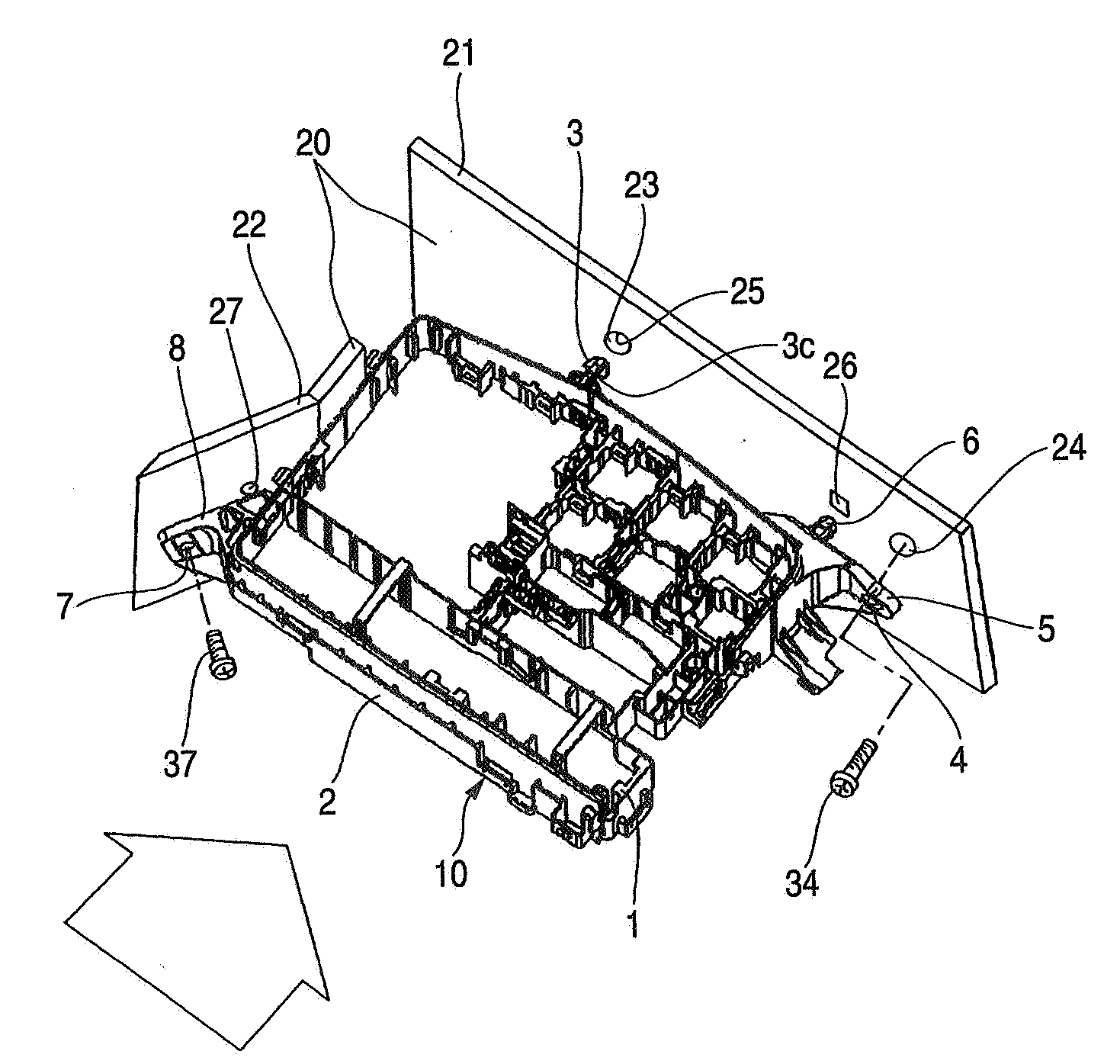
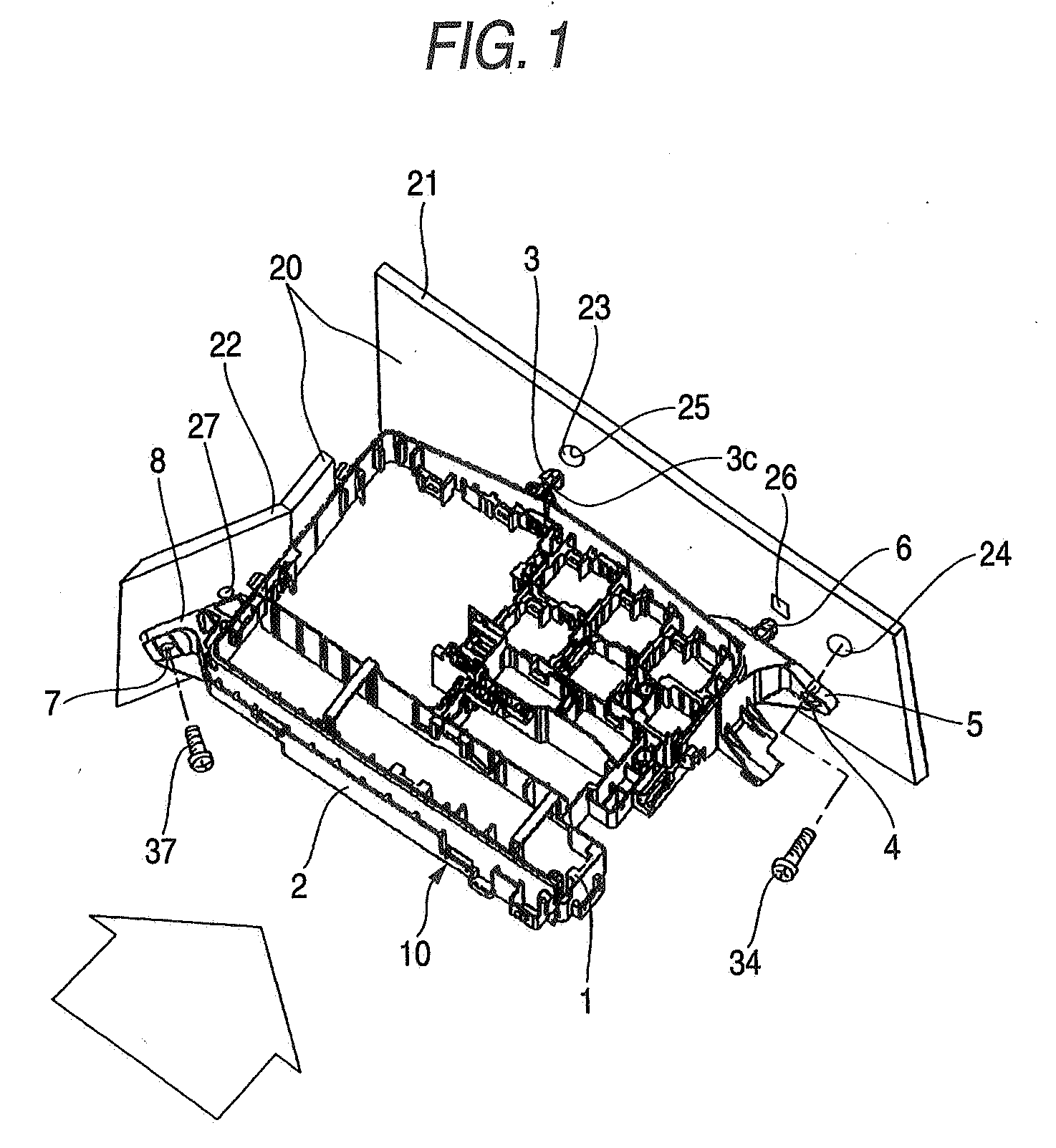
[0027]FIG. 1 is a perspective view for explaining a mounting structure for mounting one preferred embodiment of an electric connection box of the present invention on a mounting member.

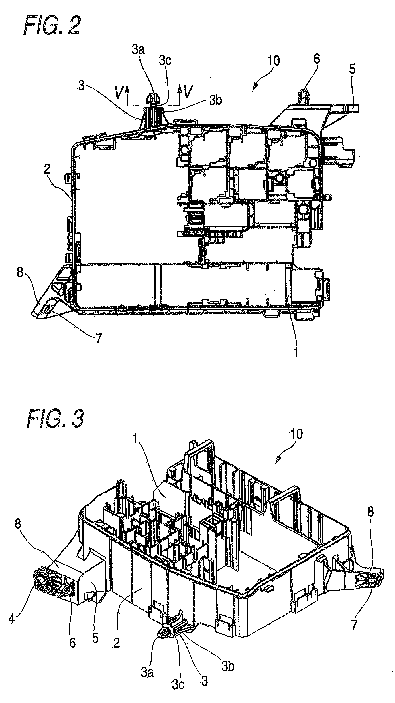
[0028]FIG. 2 is a top plan view of a connection box body of the electric connection box of this embodiment.

[0029]FIG. 3 is a perspective view of the connection box body of FIG. 2, mainly showing a provisionally-placing projection formed on an outer peripheral surface of the connection box body, a first mounting portion formed on the outer peripheral surface and having a first screw passage hole, and a second mounting portion formed on the outer peripheral surface and having a second screw passage hole.

[0030]FIG. 4 is a side-elevational view of the electric connection box having upper and lower covers attached to the connection box body.

[0031]FIG. 5 is a cross-sectional view taken along the line V-V of FIG. 2.

[0032]FIG...


PUM


Abstract

In an electric connection box, even if accuracy of a relative position between a first screw passage hole and a first screw hole, as well as accuracy of a relative position between a second screw passage hole and a second screw hole, is low, the relative positional relation between the first screw passage hole and the first screw hole, as well as the relative positional relation between the second screw passage hole and the second screw hole, can be adjusted because of the provision of a gap between an outer peripheral surface of a constricted engagement portion of a provisionally-placing projection and a hole-defining peripheral surface of a mounting member at the time of mounting a connection box body on the mounting member so that the passage of a first screw through the first screw passage hole and the first screw hole, as well as the passage of a second screw through the second screw passage hole and the second screw hole, can be easily carried out.

Description

BACKGROUND OF THE INVENTION [0001] 1. Field of the Invention [0002] This invention relates to an electric connection box (that is, an electric junction block) such as a relay box and a fuse box used in a vehicle such for example as an automobile, and more particularly to an electric connection box provided with a mounting structure for mounting a connection box body of the electric connection box (in which electric parts such as relays and fuses are received) on a mounting member such for example as a vehicle body panel of a vehicle. [0003] 2. Related Art [0004] There is known one conventional electric connection box in which the electric connection box is fixed to a bracket (mounting member) by a bolt and a nut while inserting cylindrical retaining pins (retaining projections) into respective retaining holes in the bracket (see JP-A-7-39042 Publication). [0005] For mounting this electric connection box on the bracket, the retaining pins on the electric connection box are mated resp...

Claims


Application Information

Patent Timeline
Patent Type & Authority Applications(United States)
IPC IPC(8): H02G3/08
CPCH01R13/73
Inventor KANEKO, NOBUTAKAMAEBASHI, AKEMI
Owner YAZAKI CORP
Why Eureka
Try Eureka