Eureka AIR delivers breakthrough ideas for toughest innovation challenges, trusted by R&D personnel around the world.

Eye drop aimer system

a technology of eye drop and aimer, which is applied in the field of eye drop aimer system, can solve the problems of unsanitary inconvenience and lack of lighting supply

Inactive Publication Date: 2007-03-08
LI YUSHENG
View PDF20 Cites 10 Cited by
  • Summary
  • Abstract
  • Description
  • Claims
  • Application Information

AI Technical Summary

Problems solved by technology

Eye drops are widely used, but many users simply guess, often soaking the eyelid, lashes, and cheek but missing the eye completely.
The inconveniences are unsanitary.
These systems can not satisfy that the users visually aim directly in the direction of the axial centerline of the eye dropper spout from the spout end, and can not supply lighting.

Method used


Image

  • Eye drop aimer system
  • Eye drop aimer system
  • Eye drop aimer system

Examples


Embodiment Construction

[0014] The present invention relates to a mirrored eye drop aimer system and a method of directing eye drops into the eye of a user.

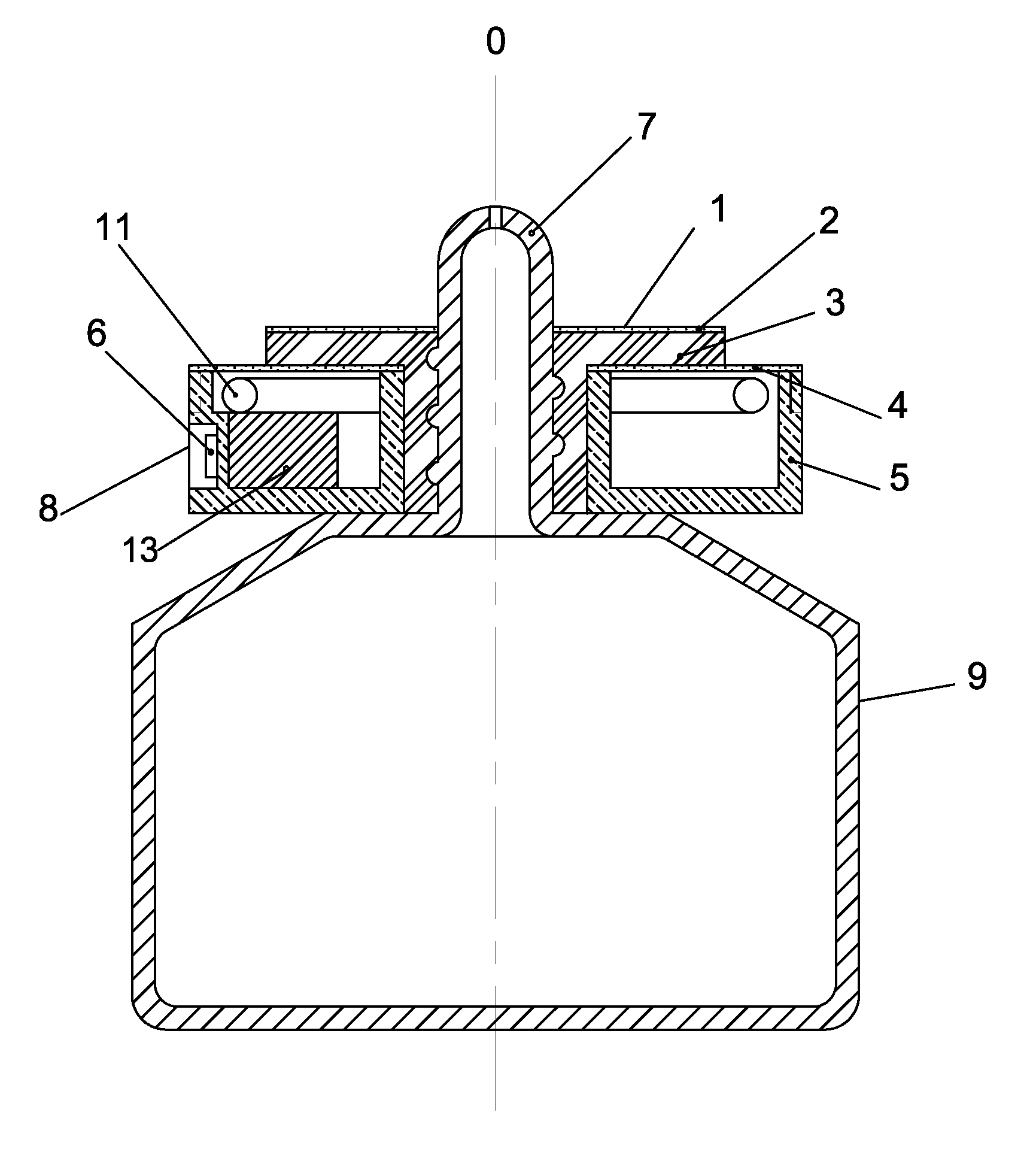
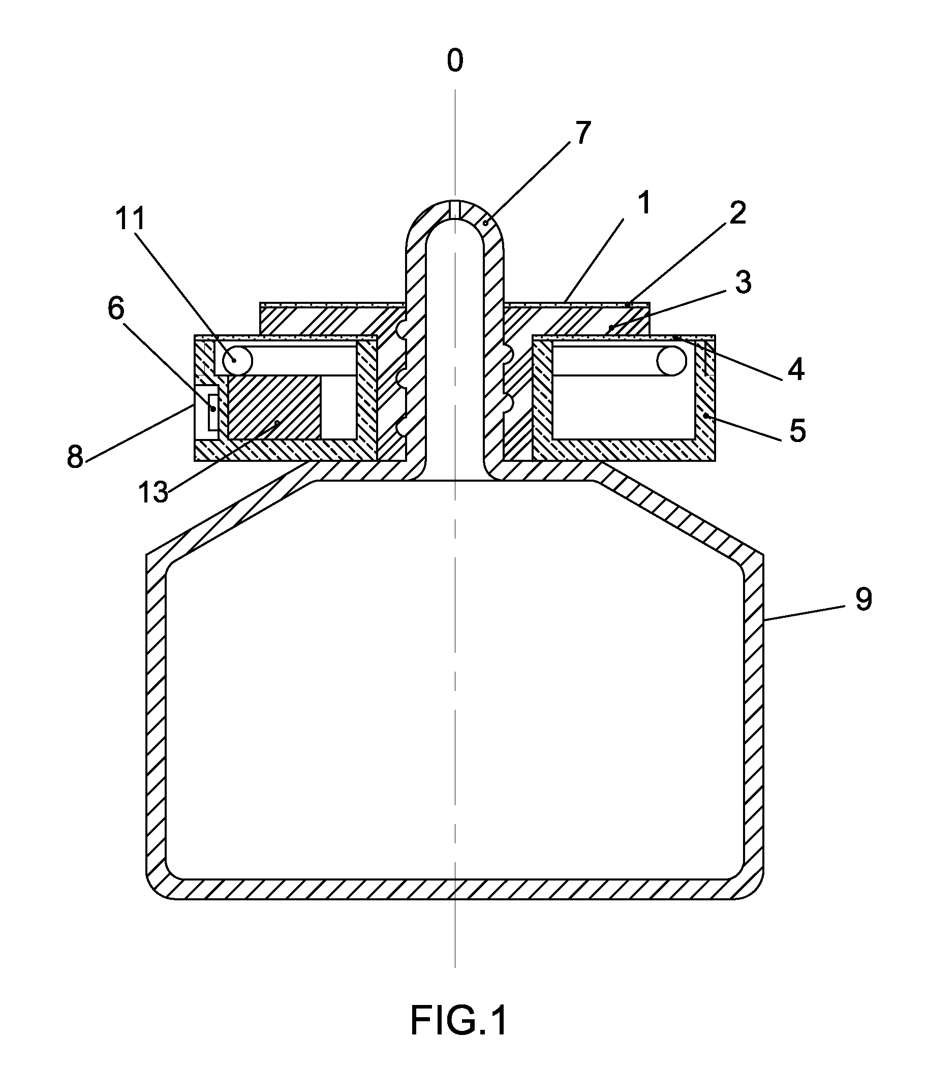
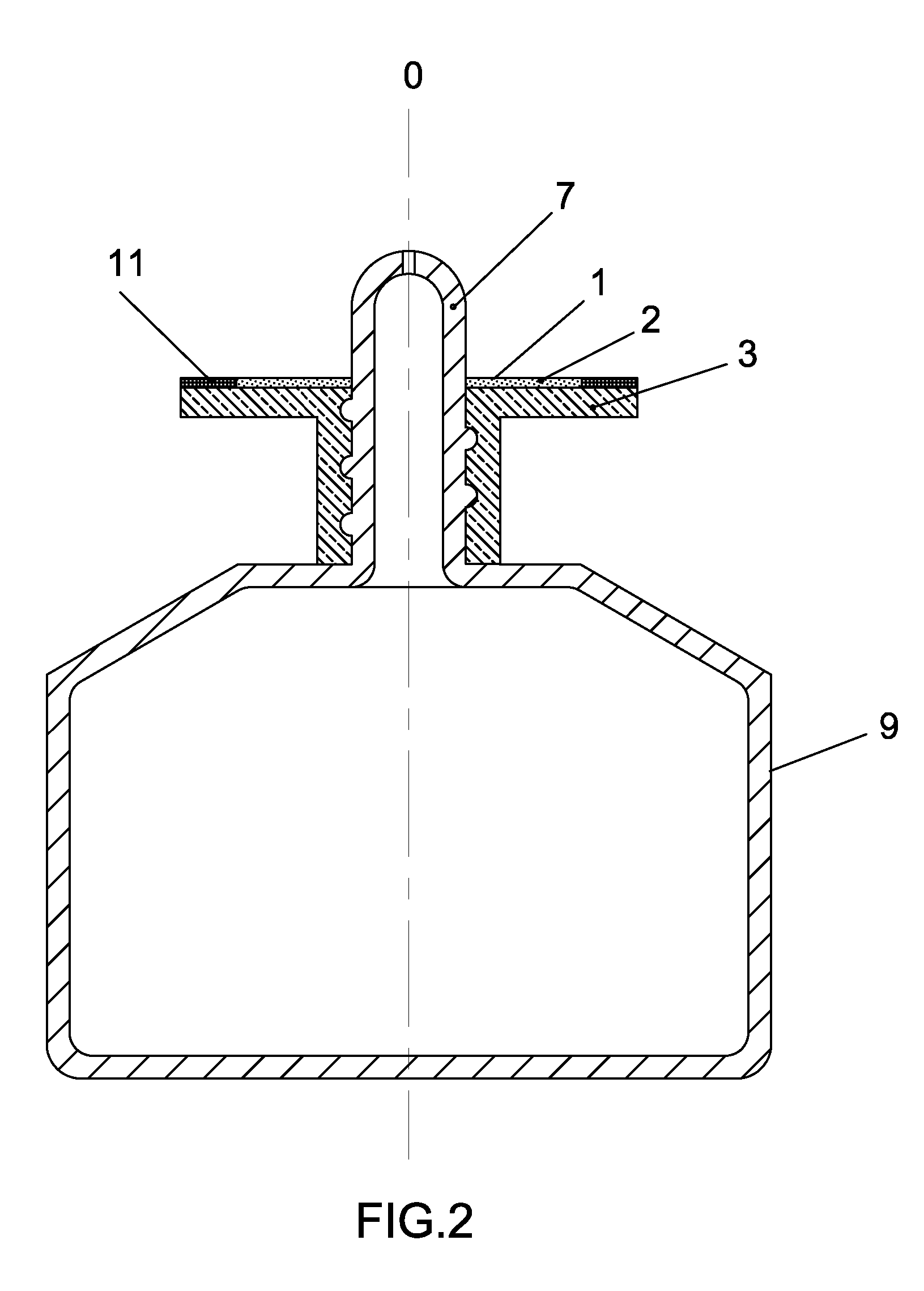
[0015]FIG. 1 diagrammatically illustrates an eye drop aimer system mounted onto an eye drop container 9. In the preferred embodiment, the major components of the eye drop aimer system include an aim instrument 1 and a light source instrument 8. The aim instrument 1 comprises a reflective surface 2 and a means 3 having an axial center hole ringing around eye drop spout 7 of the eye drop container 9. The means 3 locates the reflective surface 2 vertically around the periphery of the eye drop spout 7, additionally close to the end of the eye drop spout 7. The eye drop spout 7 has an axial center line 0.

[0016] In the preferred embodiment, the light source instrument 8 is located between the aim instrument 1 and the eye drop container 9. Other location of the light source instrument 8 on the eye drop container 9 and / or on the aim instrument 1 may be utiliz...


PUM


Abstract

The eye drop aimer system is used in connection with an eye drop container. The eye drop aimer system utilizes an aim instrument having at least one reflective surface. In a preferred embodiment, the reflective surface of the aim instrument is located vertically around the eye drop spout of the eye drop container, when the user visually aims with his or her reflected eye image in the reflective surface and the eye drop spout end, his or her head and eye are in a substantially horizontal position and the eye drop container is substantially vertically disposed, the position of the spout end seen in the reflected eye image in the reflective surface indicates the aim of the drops in the eye; a light source instrument having at least one light source is utilized to supply lighting when the users drop eye in dark and weak.

Description

[0001] This is a non-provisional patent application of U.S. provisional patent application APPL No. 60 / 714,781, filed on Sep. 7, 2005. [0002] The present invention relates to a mirrored eye drop aimer system and a method of directing eye drops into the eye of a user.BACKGROUND OF THE INVENTION [0003] Eye drops are widely used, but many users simply guess, often soaking the eyelid, lashes, and cheek but missing the eye completely. Some users simply lack the aim necessary, some users must ask for help from others. The inconveniences are unsanitary. Eye drop devices which comprise mirrors are known. U.S. Pat. No. 3,913,575 to Windsor discloses an eye dropper device which includes a swing out mirror attached to the base of the eye dropper. U.S. Pat. No. 6,325,781 B1 to Muroff discloses a mirrored eye dropper target. The mirrored end of the target is in a singular plane entirely tangential with respect to the eye dropper body. These systems can not satisfy that the users visually aim dir...

Claims


Application Information

Patent Timeline
Patent Type & Authority Applications(United States)
IPC IPC(8): A61B3/10
CPCA61M35/003A61F9/0026
Inventor LI, YUSHENG
Owner LI YUSHENG
Why Eureka
Eureka Blog
Learn More