Shaft, e.g., for an electro-mechanical surgical device

a surgical device and electromechanical technology, applied in the direction of surgical staples, surgical forceps, osteosynthesis devices, etc., can solve the problems of not providing a user, not providing moisture detection capabilities, and generally complicated and expensive assembly

Inactive Publication Date: 2007-03-08
TYCO HEALTHCARE GRP LP
View PDF19 Cites 617 Cited by
  • Summary
  • Abstract
  • Description
  • Claims
  • Application Information

AI Technical Summary

Benefits of technology

[0004] In an example embodiment of the present invention, a flexible shaft for coupling a surgical attachment with an electromechanical driver device is provided that includes a flexible, elongated outer sheath, the sheath being formed from an autoclavable material, and at least one drive shaft disposed in the outer sheath. In an example embodiment of the present invention, the flexible shaft includes a moisture sensor disposed within the outer sheath configured to detect moisture within the flexible outer sheath. The flexible shaft may also include one or more rotatable drive shafts that are connected to drive shafts of a motor system of the electromechanical driver device so as to rotate and thereby operate a surgical attachment. Each one of the rotatable drive shafts of the flexible shaft may include a tabbed quadrature ring that alternately blocks and allows light from a light source to be conveyed via fiber optic cables to a controller that is configured to detect and interpret the light signals received via the fiber optic cables and to determine, e.g., the position and / or direction of a component, e.g., an anvil or cutting blade, of the surgical attachment, e.g., a surgical stapler, in response thereto. The flexible shaft may further include additional channels for providing irrigation and / or aspiration to a surgical site via the flexible shaft.

Problems solved by technology

Generally, conventional surgical systems may include shafts that provide limited torque, may not provide a user to accurately ascertain the positions of the operative elements of associated instruments and systems, may not provide moisture detection capabilities, and may be generally complicated and expensive to assemble.

Method used


Image

  • Shaft, e.g., for an electro-mechanical surgical device
  • Shaft, e.g., for an electro-mechanical surgical device
  • Shaft, e.g., for an electro-mechanical surgical device

Examples


Embodiment Construction

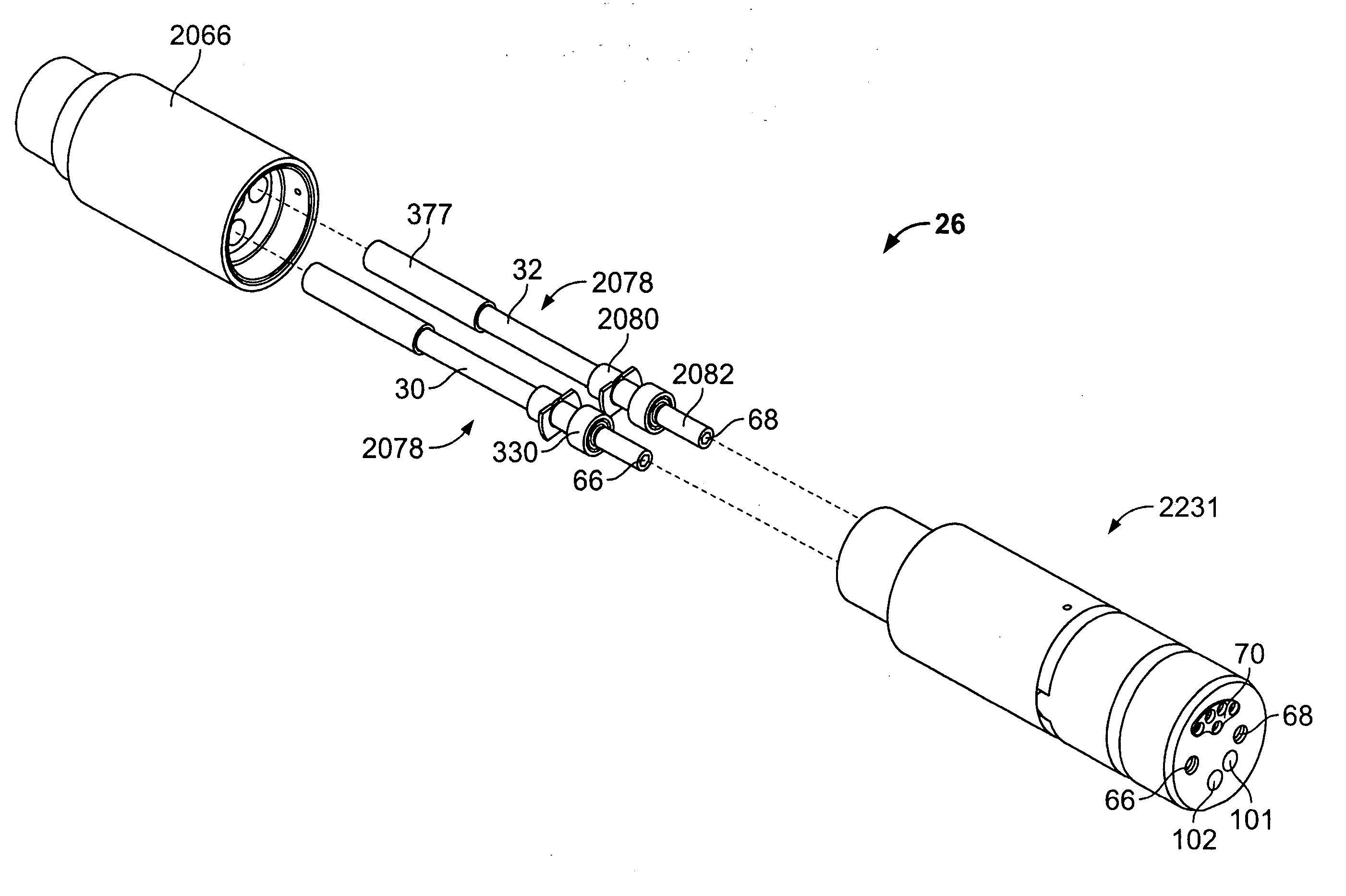
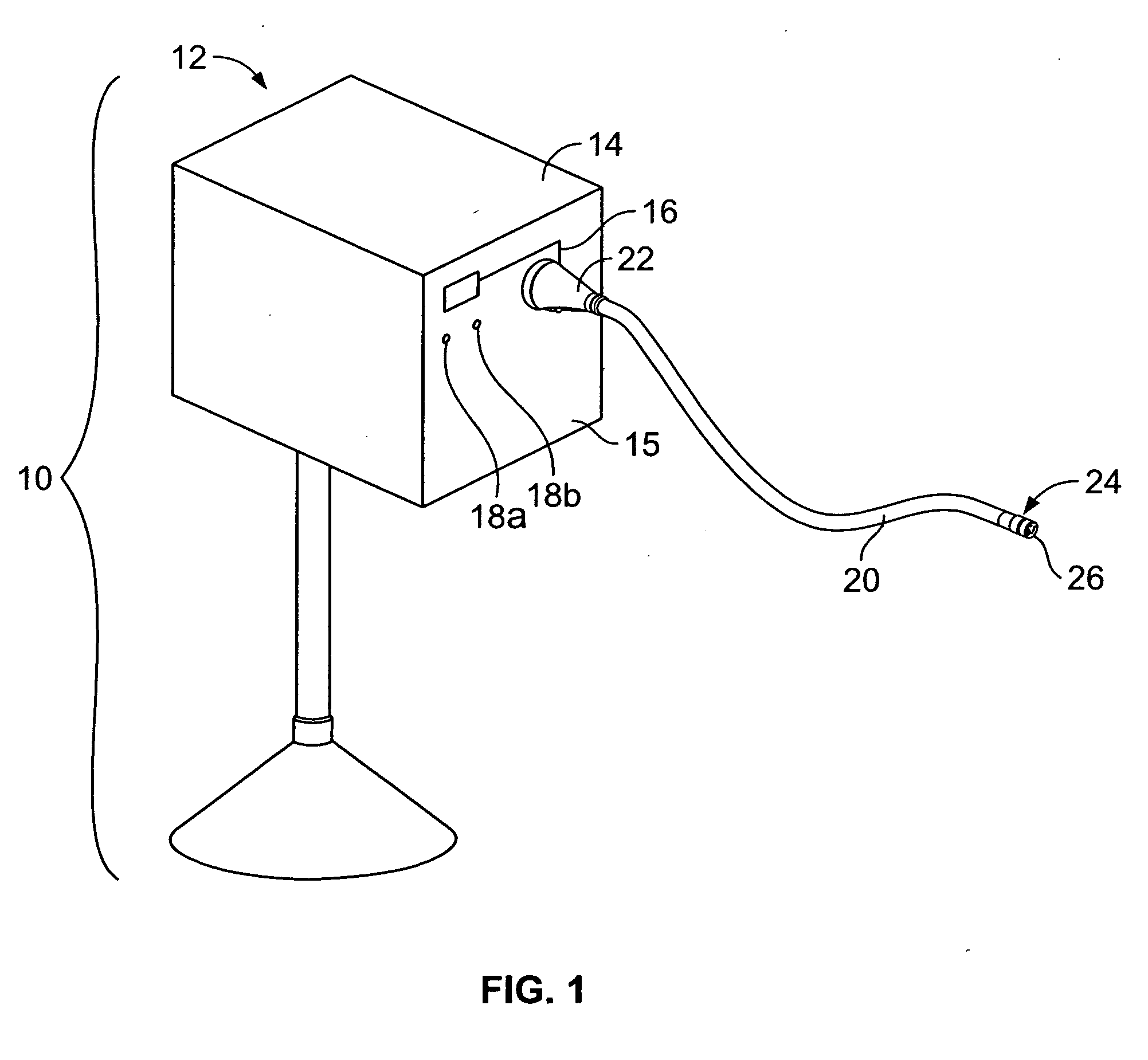
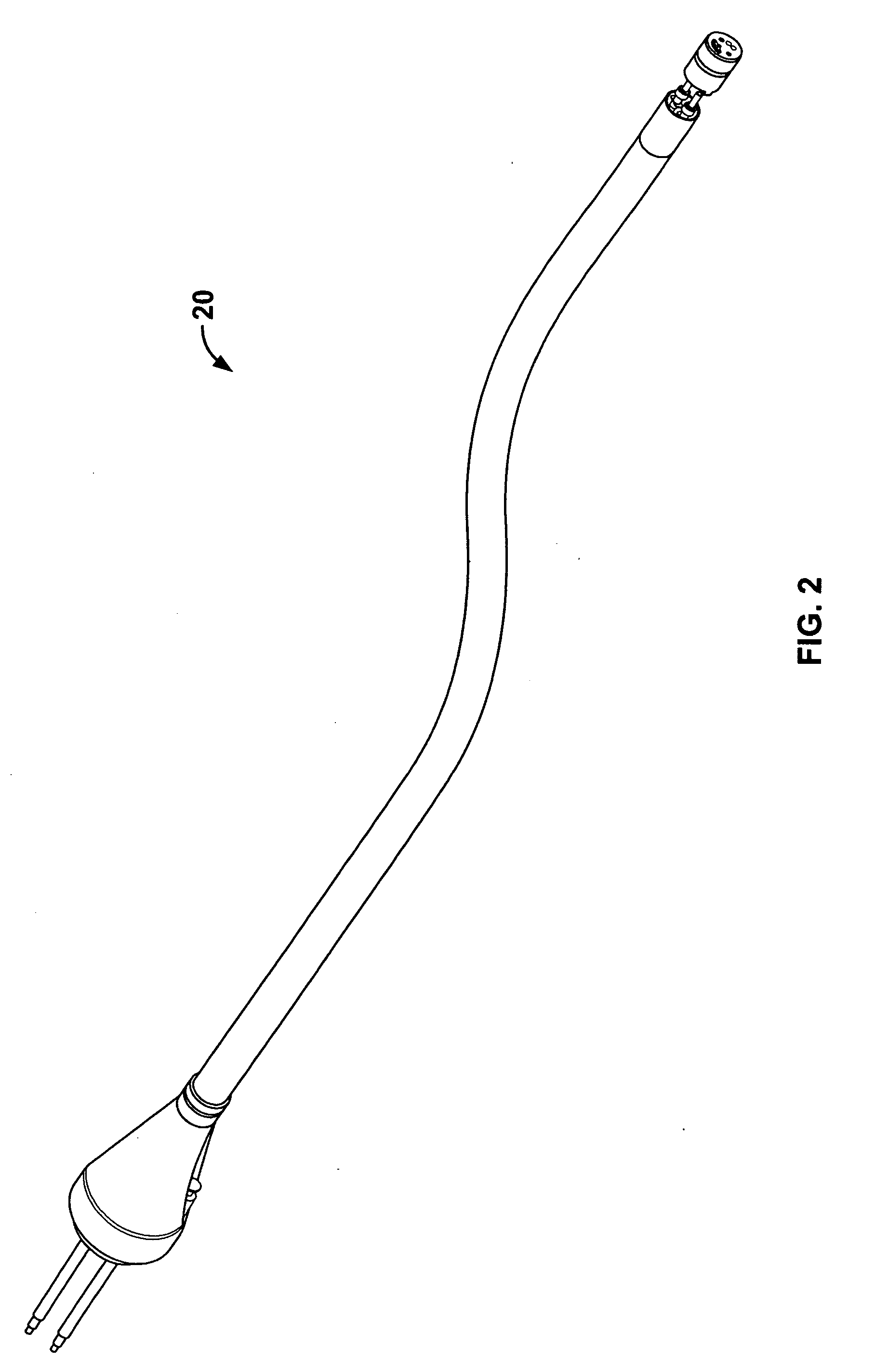
[0030] Referring to FIG. 1, there is seen a perspective view of an electromechanical surgical device 10 according to an example embodiment of the present invention. The electromechanical surgical device 10 may include, for example, a remote power console 12, which includes a housing 14 having a front panel 15. Mounted on the front panel 15 are a display device 16 and indicators 18a, 18b, which are more fully described hereinbelow. A shaft 20 may extend from the housing 14 and may be detachably secured thereto via a first coupling 22. The shaft 20 may be flexible, rigid, articulable, articulatable, etc. Although the shaft 20 is referred to below as a flexible shaft 20, it should be understood that reference to a flexible shaft 20 is merely one example embodiment of the shaft 20 and that the shaft 20 is in no way limited to a flexible arrangement. The distal end 24 of the flexible shaft 20 may include a second coupling 26 adapted to detachably secure a surgical instrument or attachmen...


PUM


Abstract

A shaft being, e.g., flexible, that includes an elongated outer sheath, at least one drive shaft disposed within the outer sheath and a ring non-rotatably mounted on the at least one rotatable drive shaft and at least one light source mounted within the shaft, such that, upon rotation of the at least one rotatable drive shaft, the ring alternately blocks and allows light from the light source to be detected. The shaft may also include a moisture sensor disposed within the outer sheath of the shaft and configured to detect moisture within the outer sheath. The shaft may include couplings that connect a distal end of the outer sheath to a surgical attachment and a proximal end of the outer sheath to a remote power console.

Description

CROSS-REFERENCE TO RELATED APPLICATIONS [0001] This application claims the benefit of U.S. Provisional Patent Application Ser. No. 60 / 703,227, entitled “Flexible Shaft, e.g., for an Electro-Mechanical Surgical Device”, filed Jul. 27, 2005, which is expressly incorporated herein in its entirety by reference thereto.FIELD OF THE INVENTION [0002] The present invention relates to a shaft, and more particularly, to a shaft for use with an electromechanical surgical device. BACKGROUND INFORMATION [0003] Various surgical systems are known. For instance, a surgical system may include an electromechanical driver device detachably coupled to a surgical attachment. Such an electromechanical driver device is described in, for example, U.S. patent application Ser. No. 09 / 723,715, entitled “Electro-Mechanical Surgical Device,” filed on Nov. 28, 2000, now issued as U.S. Pat. No. 6,793,652, U.S. patent application Ser. No. 09 / 836,781, entitled “Electro-Mechanical Surgical Device, filed on Apr. 17, ...

Claims


Application Information

Patent Timeline
Patent Type & Authority Applications(United States)
IPC IPC(8): A61B17/00
CPCA61B17/00234A61B2217/005A61B17/115A61B17/1285A61B17/7208A61B19/22A61B19/44A61B2017/00026A61B2017/00119A61B2017/00199A61B2017/00398A61B2017/00464A61B2017/00853A61B2017/2905A61B2019/2242A61B2019/2276A61B2019/467A61B2019/4815A61B2019/4857A61B2019/5206A61B17/068A61B2034/742A61B34/71A61B2090/067A61B90/90A61B2090/0803A61B2090/0811A61B2090/306A61B34/70F16C1/06A61B34/74A61B90/06A61B90/08A61B90/30A61B17/1155A61B2017/00323A61B2217/007H04B10/25
Inventor WHITMAN, MICHAEL P.MALINOUSKAS, DONALD T.
Owner TYCO HEALTHCARE GRP LP
Why Eureka
Try Eureka