Inssertion depth-adjustable needle insertion device

a needle insertion device and depth adjustment technology, applied in the field of lancing equipment, can solve the problems of increasing the risk of breaking the adjustment mechanism, not easy, and requiring troublesome work on the user

Inactive Publication Date: 2007-03-08
ARKRAY INC
View PDF20 Cites 113 Cited by
  • Summary
  • Abstract
  • Description
  • Claims
  • Application Information

AI Technical Summary

Benefits of technology

[0009] An object of the present invention is to enable hygienic lancing depth adjustment stably for a long period of time without requiring complicated maintenance.
[0010] According to a first aspect of the present invention, there is provided a lancing depth-adjustable lancing apparatus for moving a lancing element held in a housing in a lancing direction to lance skin with the lancing element, the lancing apparatus comprising a lancing depth adjustment mechanism for adjusting lancing depth of the lancing element in the skin; wherein the lancing depth adjustment mechanism comprises a displacing member which is movable relative to the housing in the lancing direction or in a retreating direction which is opposite from the lancing direction, a cover which is movable with the displacing member in the lancing and the retreating directions, and a stepped portion provided at the housing for restricting the movement of the lancing element in the lancing direction when the lancing element moves in the lancing direction.

Problems solved by technology

However, the adjustment mechanism 9A, 9B is to be attached to or detached from the main body of a lancing apparatus in the assembled state, and the operation for disassembling the adjustment mechanism 9A, 9B is not easy and forces a troublesome work on the user.
Further, frequent disassembling and assembling of the adjustment mechanism 9A, 9B increases the risk of breaking the adjustment mechanism 9A, 9B or losing parts such as outer sleeve 92A, 92B.
The cleaning of a plurality of complicated parts is troublesome, and there is a high possibility that some portions remain uncleaned.
In such a case, the possibility that some portions remain uncleaned increases.

Method used


Image

  • Inssertion depth-adjustable needle insertion device
  • Inssertion depth-adjustable needle insertion device
  • Inssertion depth-adjustable needle insertion device

Examples


first embodiment

[0048] First, with reference to FIGS. 1 through 11, the present invention will be described.

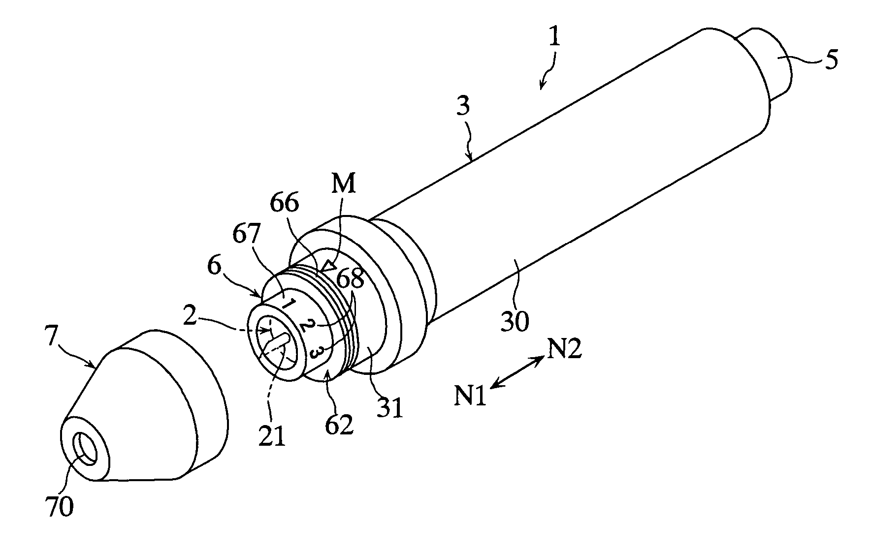
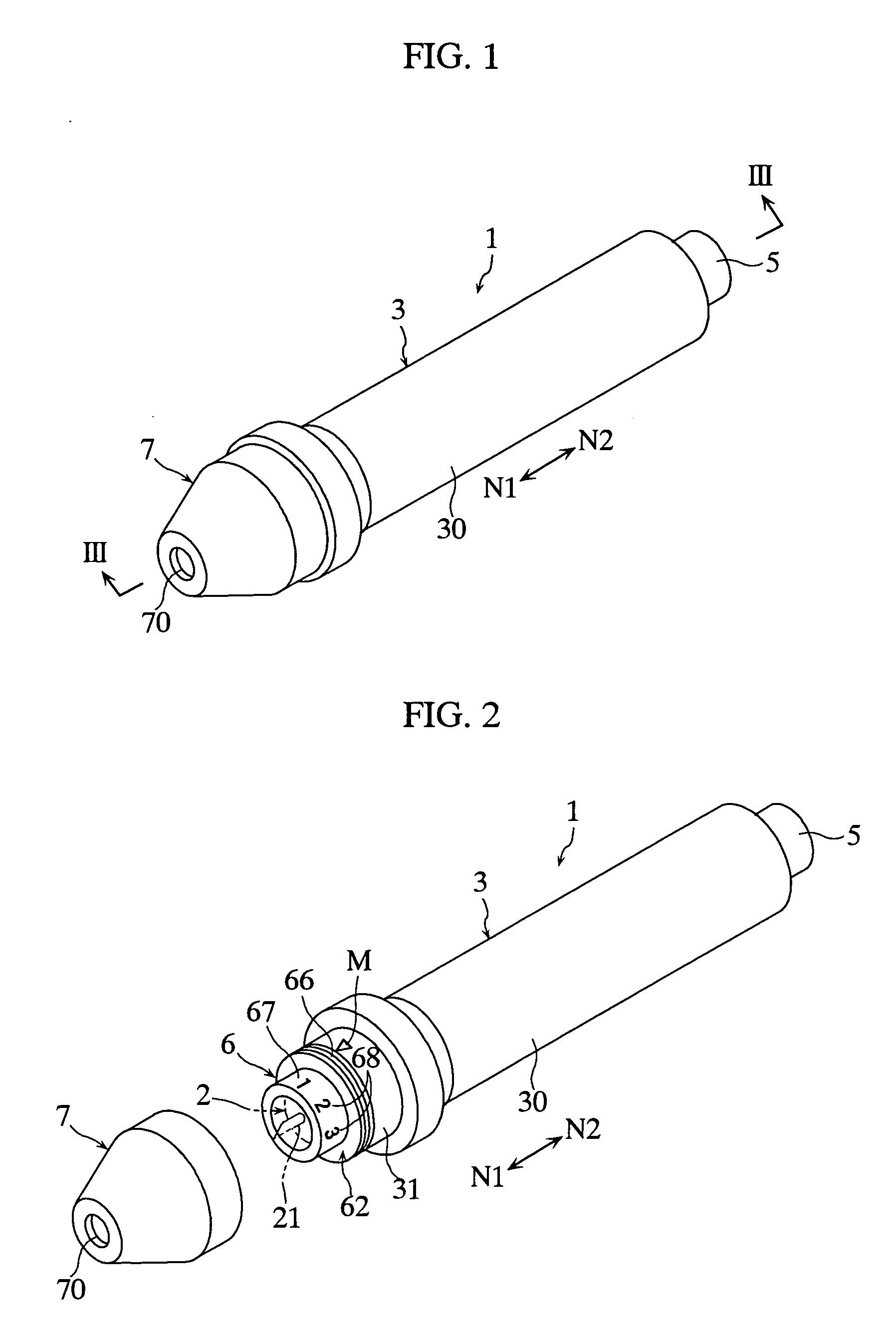
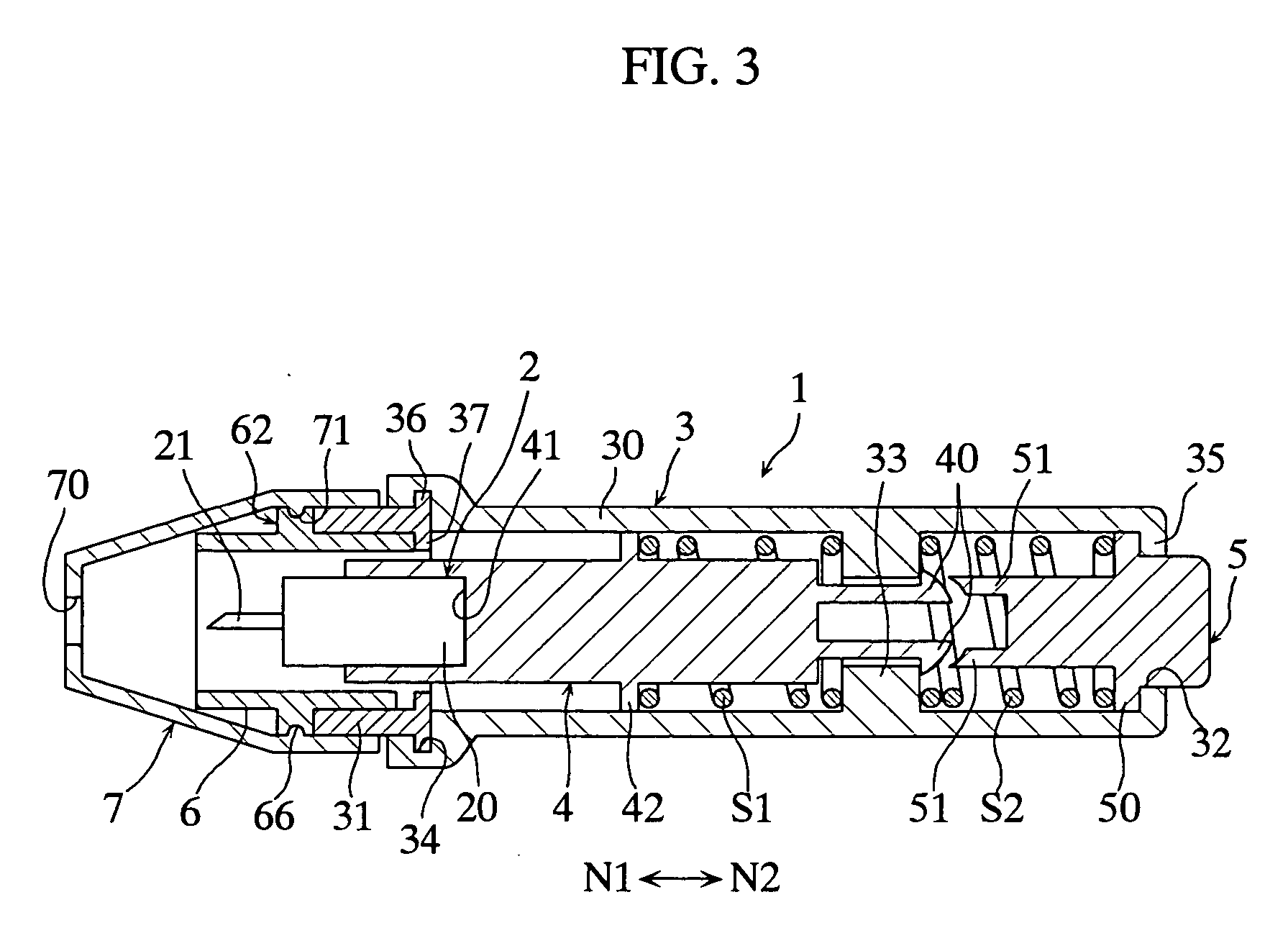
[0049] The lancing apparatus 1 shown in FIGS. 1-3 is used with a lancet 2 mounted thereto. The lancet 2 includes a main body 20, and a needle 21 projecting from the main body. For example, in molding the main body 20 using synthetic resin, the needle 21 is integrally formed on the main body 20 by insert molding.

[0050] The lancing apparatus 1 includes a housing 3, a lancet holder 4, an operation cap 5, a rotatable member 6 and a cover 7.

[0051] The housing 3 accommodates the lancet holder 4. The housing 3 includes a main body 30, and a guide member 31 fixed to the main body.

[0052] The main body 30 includes a through-hole 32, a projection 33 and an annular recess 34. The through-hole 32, which allows the movement of the operation cap 5, is provided at an upper wall 35 of the housing 3. The projection 33 serves to hold coil springs S1 and S2 and engage with the lancet holder 4. The annular rec...

third embodiment

[0079] A lancing apparatus according to the present invention will be described below with reference to FIG. 14.

[0080] The lancing apparatus 1C shown in FIG. 14 includes a lancing depth adjustment mechanism which is different from that of the first embodiment. The lancing depth adjustment mechanism includes a guide member 31C, a rotatable member 6C and a cover 7C.

[0081] The guide member 31C is non-rotatably fixed to the main body 30C of the housing 3C. The rotatable member 6C is threadingly engaged with the guide member 31C and is movable in the lancing or the retreating direction N1, N2 when rotated around the lancing or the retreating direction N1, N2. The rotatable member 6C includes a flange portion 69C for engaging the lancet holder 4C. The cover 7C is attached to the guide member 31C rotatably but so as not to move in the lancing and the retreating directions N1, N2 and is detachable from the guide member 31C.

[0082] With the above arrangement, by rotating the rotatable membe...

fourth embodiment

[0084] Next, a lancing apparatus according to the present invention will be described below with reference to FIGS. 15-18C.

[0085] The lancing apparatus 1D shown in FIGS. 15-17 is designed to adjust the lancing depth by utilizing a cam mechanism 8D and includes a housing 3D, a lancet holder 4D, a displacing member 6D and a cover 7D.

[0086] The cam mechanism 8D includes a first groove 80D, a second groove 81D and an operation member 82D. The first groove 80D penetrates through the housing 3D and is inclined with respect to the lancing and the retreating directions N1, N2. The second groove 81D is formed at the displacing member 6D so as not to penetrate therethrough and extends perpendicularly to the lancing and the retreating directions N1, N2. The operation member 82D includes a shaft portion 83D which is movable through the first and the second grooves 80D and 81D.

[0087] Although the configurations of the housing 3D, the lancet holder 4D and the cover 7D differ from those of the f...


PUM


Abstract

The present invention relates to a lancing depth-adjustable lancing apparatus (1) for moving a lancing element (21) held in a housing (3) in a lancing direction (N1) to lance skin with the lancing element (21). The lancing apparatus (1) includes a lancing depth adjustment mechanism for adjusting lancing depth of the lancing element (21) in the skin. The lancing depth adjustment mechanism includes a displacing member (6) which is movable relative to the housing (3) in the lancing or the retreating direction (N1, N2), a cover (7) which is movable with the displacing member (6) in the lancing or the retreating directions (N1, N2), and a stepped portion (37) provided at the housing (3) for restricting the movement of the lancing element (21) in the lancing direction (N1) when the lancing element (21) moves in the lancing direction (N1).

Description

TECHNICAL FIELD [0001] The present invention relates to a lancing apparatus for moving a lancing element to lance skin with the lancing element. Specifically, the present invention relates to a lancing apparatus capable of adjusting the lancing depth of the lancing element in the skin. BACKGROUND ART [0002] As an adjustment mechanism for adjusting the lancing depth in a lancing apparatus, a mechanism is known which includes three members, i.e. an inner sleeve, an intermediate ring and an external sleeve, as already disclosed (See Patent Documents 1 and 2, for example). [0003] Specifically, as shown in FIGS. 19A and 19B of the present application, in the adjustment mechanism disclosed in Patent Document 1, the intermediate ring 91A is fixed to the inner sleeve 90A, and the outer sleeve 92A moves relative to the intermediate ring 91A in the direction indicated by the arrows N1 and N2 in the figures. The intermediate ring 91A has an inclined end surface 93A on the arrow N1 side. The ou...

Claims


Application Information

Patent Timeline
Patent Type & Authority Applications(United States)
IPC IPC(8): A61B17/32A61B5/151A61B5/15
CPCA61B5/1411A61B2018/00738A61B5/15186A61B5/150022A61B5/150183A61B5/150412A61B5/150549A61B5/150618A61B5/150717A61B5/150824A61B5/15113A61B5/15128A61B5/1513A61B5/1519A61B5/15194
Inventor UEHATA, YOSHIHARUFUKUZAWA, MASAHIRO
Owner ARKRAY INC
Why Eureka
Try Eureka