
Combination ceiling fan with light and sound generator

a ceiling fan and generator technology, applied in the field of ceiling fans, can solve the problems of not offering the utility of lights, sound, motion detection, and changeable blades, and the removal of a number of blades from ceiling fans is normally not a desirable featur

Inactive Publication Date: 2007-03-15
GOMEZ ANGEL C
View PDF16 Cites 44 Cited by
  • Summary
  • Abstract
  • Description
  • Claims
  • Application Information

AI Technical Summary

Benefits of technology

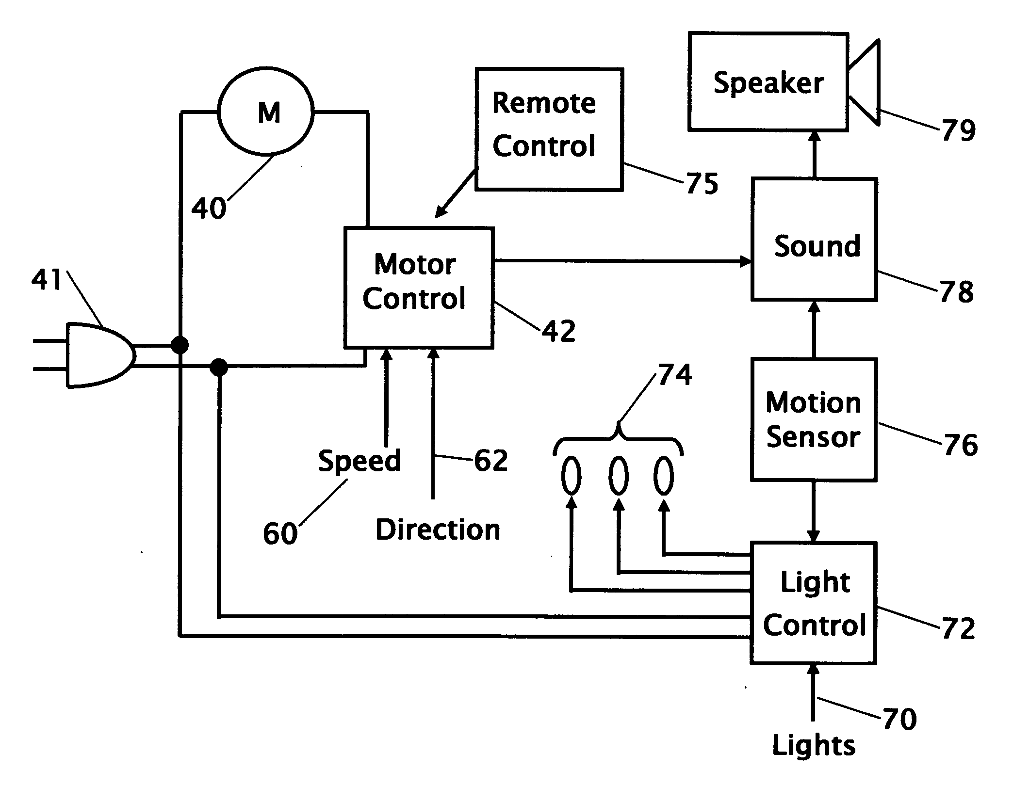
[0011] Another object of the invention is to provide a helicopter-ceiling fan with lanyards that control the fan speed direction and lights. The lanyards may be provided with figurines of solders repelling from the helicopter. The lanyards may also allow the setting or adjustment of the sounds that can be made from the helicopter.

Problems solved by technology

While all these products have been produced separately, none have been produced that provide a combination of all the components in a single product.
All of these patents are for the ornamental design of a ceiling fan with a helicopter body, but none of them offer the utility of lights, changeable number of blades, sounds, or motion detection.
The removal of a number of blades from ceiling fans is normally not a desirable feature because less airflow may result with the removal of blades.
Ceiling fans that are available today do not offer changeable blades with the functions of helicopter lighting, sounds, or motion detection.
None of these patents are for the combination with a ceiling fan and further do not cover the combination of motion detection with a ceiling fan and sound production.
They further do not cover the utility of lights, changeable number of blades, sounds, or motion detection.
All of these patents are for sound generating devices, but none of them are for a combination with a ceiling fan or a ceiling fan with lights, changeable number of blades or motion detection.

Method used


Image

  • Combination ceiling fan with light and sound generator
  • Combination ceiling fan with light and sound generator
  • Combination ceiling fan with light and sound generator

Examples


Embodiment Construction

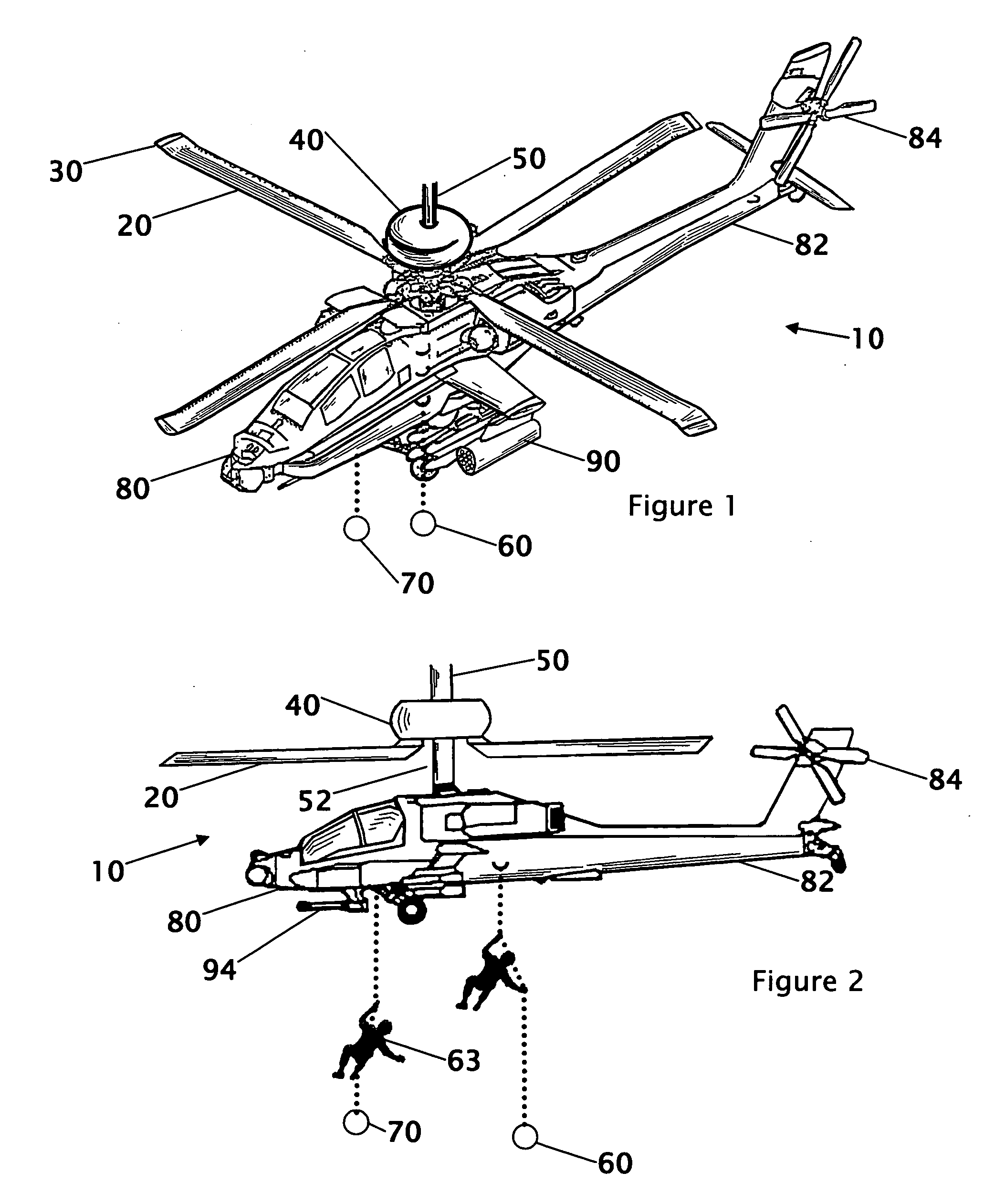
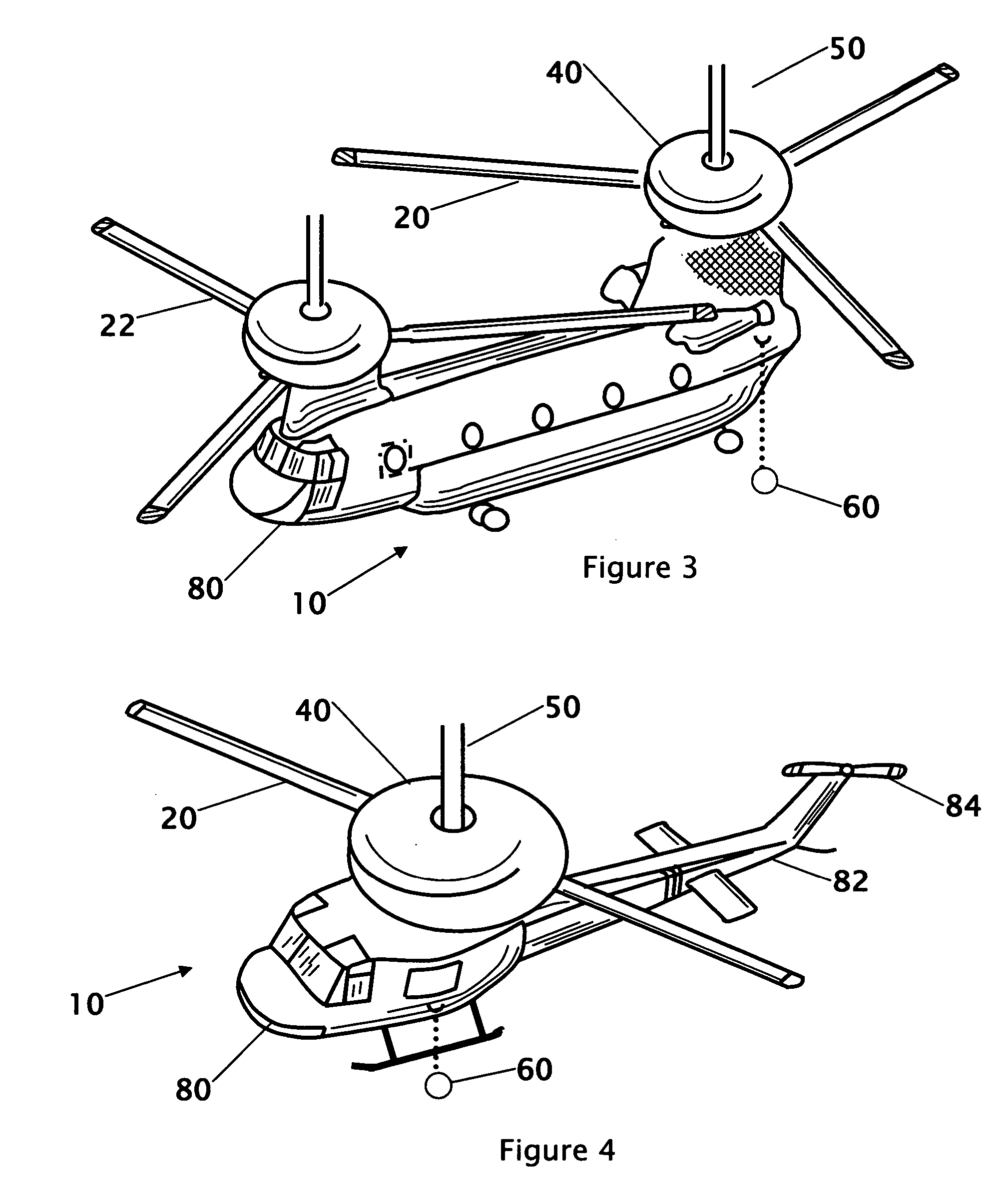
[0027] Referring to FIGS. 1-5 show different body and rotor configurations for the helicopter ceiling fan. FIG. 1 is isometric view of an Apache helicopter ceiling fan 10. FIG. 2 is a side view of an Apache helicopter ceiling fan 10. FIG. 3 is an isometric view of a Sea Knight helicopter-ceiling fan 10. FIG. 4 is an isometric view of a Huey helicopter-ceiling fan 10. FIG. 5 is an isometric view of a Sea Dragon helicopter-ceiling fan 10. These figures show four different types of helicopter bodies with rotors from two to six blades. The showing of these four different body and blade configurations is reflective of a sample of the configurations that are contemplated. A list of helicopters contemplated include but is not limited to Super Cobra, Apache, Chinook, Huey, Super Stallion, Seahawk, Pave Hawk, Pave Low IIIE, Comanche, Sea Ranger, Blackhawk, Little Bird”, Sea Knight, Sea Stallion, Sea King, Dolphin, Sea Dragon, Kiowa Warrior, Seahawk and Iroquois. In addition to the various bo...


PUM


Abstract

A ceiling fan with a light and sound generator is disclosed where the blades of the ceiling fan resemble the rotor blades of a helicopter. Under the blades of the ceiling fan a fixed or replaceable body of a helicopter is located or locatable. The blades of the helicopter may also be changeable to simulate different types of rotors for different helicopters. Control chains extend down from the body of the helicopter to resemble lanyards for repelling from the helicopter. The control chains provide control for fan speed, rotation direction, lighting, and may further include control of sounds that can be generated from the ceiling fan that may simulate commands from the pilot of a helicopter. A remote control can be provided to control the fan light and sound functions. A sensor for detecting the presence of a person in the room may also activate the sound generation.

Description

CROSS REFERENCE TO RELATED APPLICATION [0001] This application is a continuation-in-part of applicant's co-pending application Ser. No. 29 / 231,777 filed Jun. 8, 2005.DESCRIPTION FIELD OF THE INVENTION [0002] This invention relates to a ceiling fan with changeable blades, light and sound generator. More particularly, the present invention relates to a ceiling fan where the blades of the ceiling fan resemble the rotor blades of a helicopter. The body of a helicopter extends from under the blades of the ceiling fan. The control chains from the fan extend down from the body of the helicopter to resemble lanyards for repelling from the helicopter. The control chains further provide control of the fan speed, direction of rotation, lighting, and may further include control of sounds that can be generated from the ceiling fan that may simulate commands from the pilot of a helicopter. The sounds can also include “radio traffic” such as between the command pilot and gunners, co-pilots, crew c...

Claims


Application Information

Patent Timeline
IPC IPC(8): G08B3/00
CPCF04D29/005F04D25/088
Inventor GOMEZ, ANGEL C.
Owner GOMEZ ANGEL C
Learn More