Parking lock mechanism of automatic transmission

Inactive Publication Date: 2007-03-22
TOYOTA JIDOSHA KK
View PDF3 Cites 8 Cited by
  • Summary
  • Abstract
  • Description
  • Claims
  • Application Information

AI Technical Summary

Benefits of technology

[0009] An object of the present invention is to provide a parking lock mechanism of an automatic transmission capable of achieving smaller number of parts and weight. Another object of the present invention is

Problems solved by technology

Separately providing a guide member for implementing the guide portion, however, leads to increase in the number of parts.
In addition, if a spa

Method used


Image

  • Parking lock mechanism of automatic transmission
  • Parking lock mechanism of automatic transmission
  • Parking lock mechanism of automatic transmission

Examples


Example

[0023] An embodiment of a parking lock mechanism of an automatic transmission according to the present invention will be described hereinafter. The same or corresponding elements have the same reference characters allotted, and detailed description thereof may not be repeated.

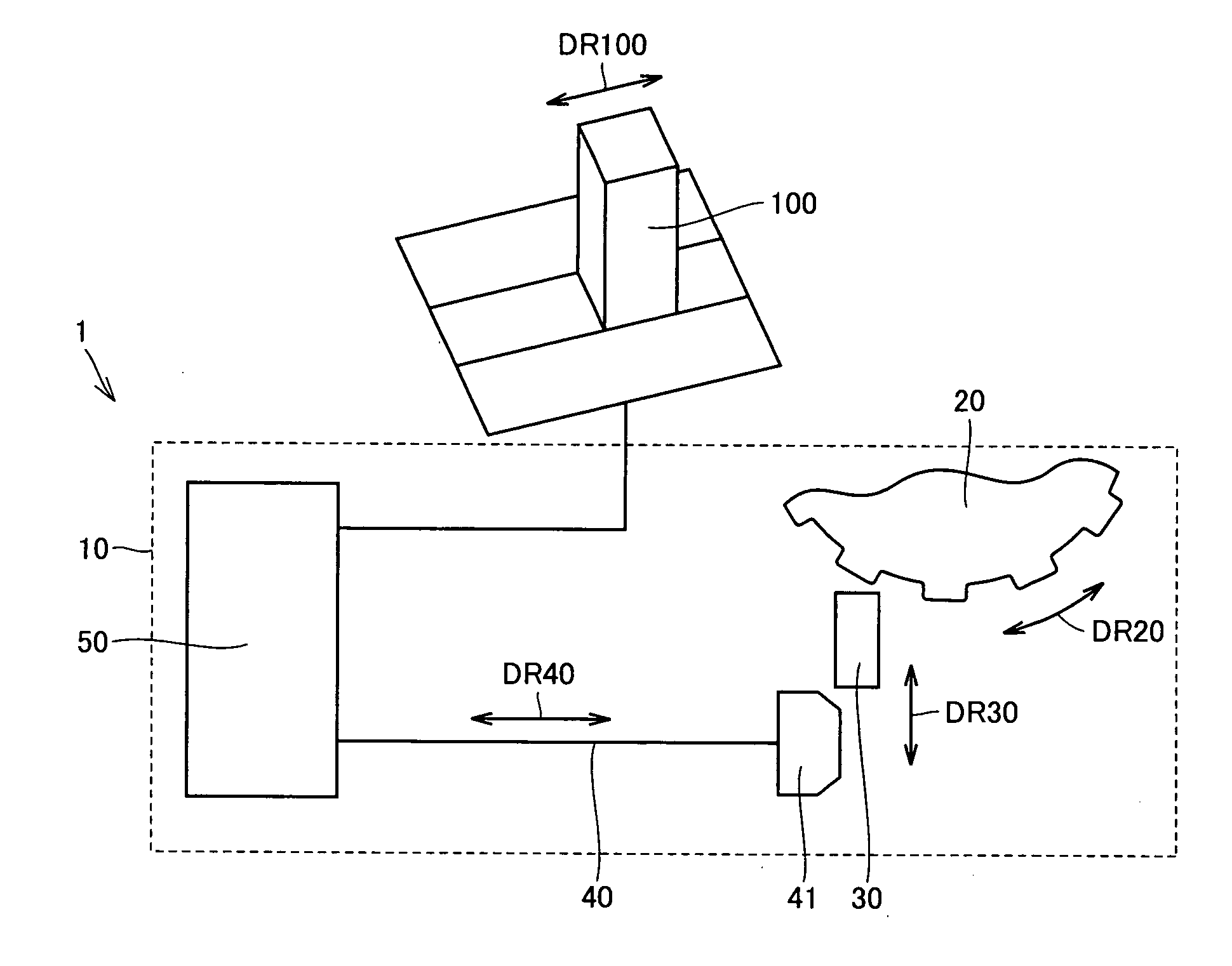
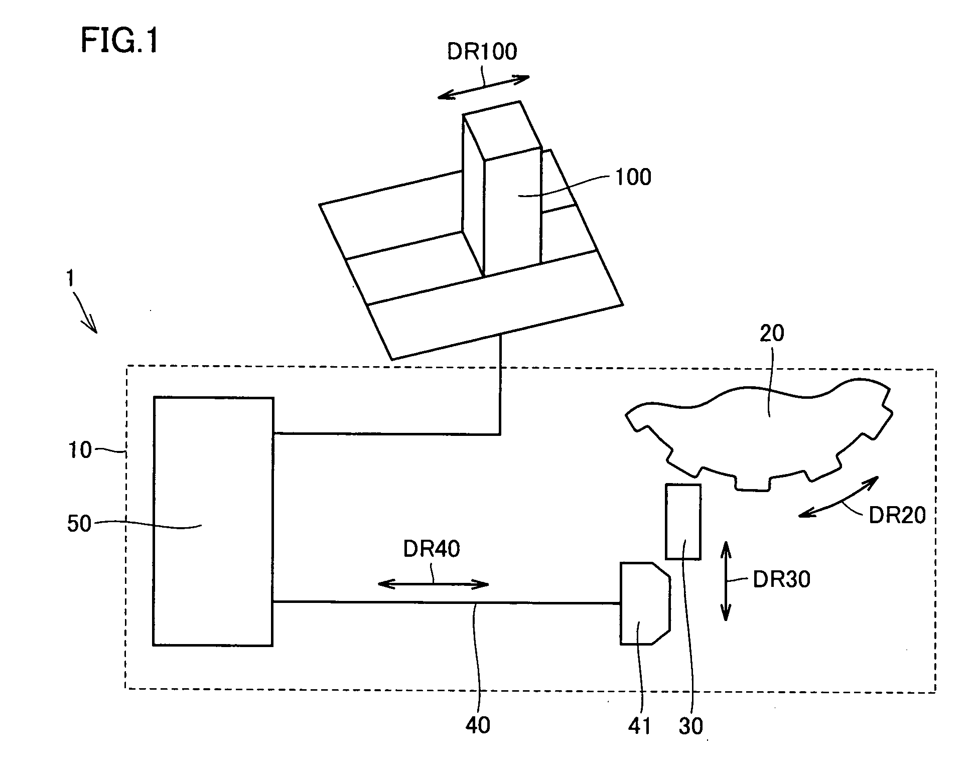
[0024]FIG. 1 shows a structure of a parking lock mechanism of an automatic transmission according to one embodiment of the present invention. Referring to FIG. 1, a parking lock mechanism 1 includes a parking gear 20 provided in a casing 10 (such as a transmission case), a parking pawl 30, a parking rod 40, and a transmission mechanism 50.

[0025] Parking gear 20 is connected to an output shaft of a powertrain of a vehicle and rotates in a direction of arrow DR20 when the vehicle runs. When parking gear 20 is engaged with parking pawl 30, the output shaft connected to a drive shaft of the vehicle is fixed. A parking lock state is thus achieved.

[0026] Parking rod 40 is connected to a selector lever 100 selectin...


PUM


Abstract

A parking lock mechanism of an automatic transmission includes a parking gear provided in a casing, a parking pawl engaged with the parking gear to achieve a parking lock state, a parking rod moving in an axial direction to press the parking pawl against the parking gear, and a guide portion guiding movement of the parking rod in the axial direction. The guide portion is formed with a casing.

Description

[0001] This nonprovisional application is based on Japanese Patent Application No. 2005-274305 filed with the Japan Patent Office on Sep. 21, 2005, the entire contents of which are hereby incorporated by reference. FIELD OF THE INVENTION [0002] The present invention relates to a parking lock mechanism of an automatic transmission, and more particularly to a parking lock mechanism of an automatic transmission having a guide portion guiding movement of a parking rod in an axial direction. DESCRIPTION OF THE BACKGROUND ART [0003] A parking lock mechanism of an automatic transmission has conventionally been known. [0004] For example, Japanese Patent Laying-Open No. 07-144616 (Patent Document 1) discloses a parking lock device achieving a park lock state by causing a parking pawl to pivot toward a parking gear such that a pawl at the tip end is engaged with a tooth of the parking gear. Here, a guide for guiding a cam fitted with looseness onto a parking rod is provided in a transmission ...

Claims


Application Information

Patent Timeline
IPC IPC(8): B60W10/10B60T1/06F16H63/34
CPCF16H63/3425F16H63/3416
Inventor KUSAMOTO, DAISUKEYASUDA, YUJIMIYAZAKI, TERUFUMI
Owner TOYOTA JIDOSHA KK
Why Eureka
Try Eureka