
Aerial support structure and method for image capture

a technology of image capture and support structure, which is applied in the direction of instruments, stands/trestles, camera body details, etc., can solve the problem that prior art image capture mechanisms are typically difficult to construct and employ

Inactive Publication Date: 2007-03-22
WAVECAM MEDIA
View PDF52 Cites 86 Cited by
  • Summary
  • Abstract
  • Description
  • Claims
  • Application Information

AI Technical Summary

Benefits of technology

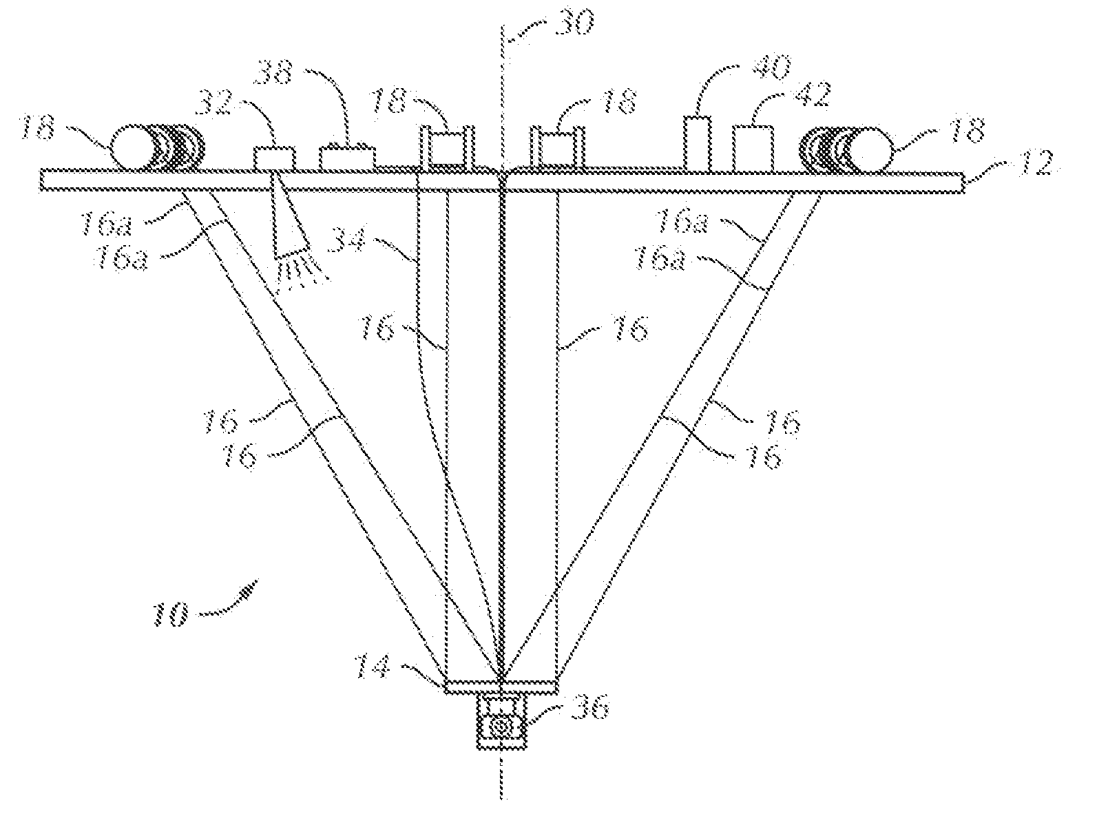
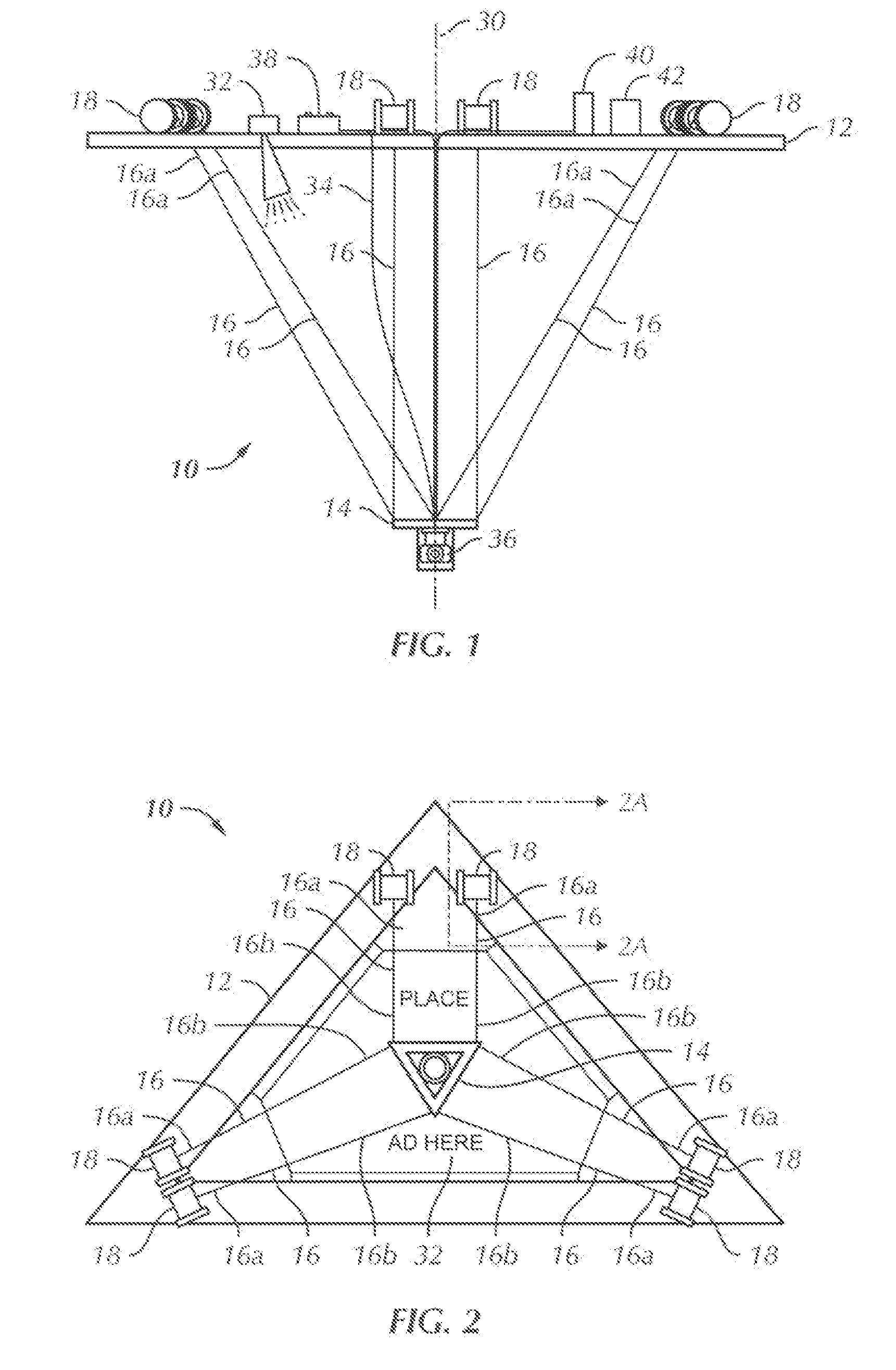
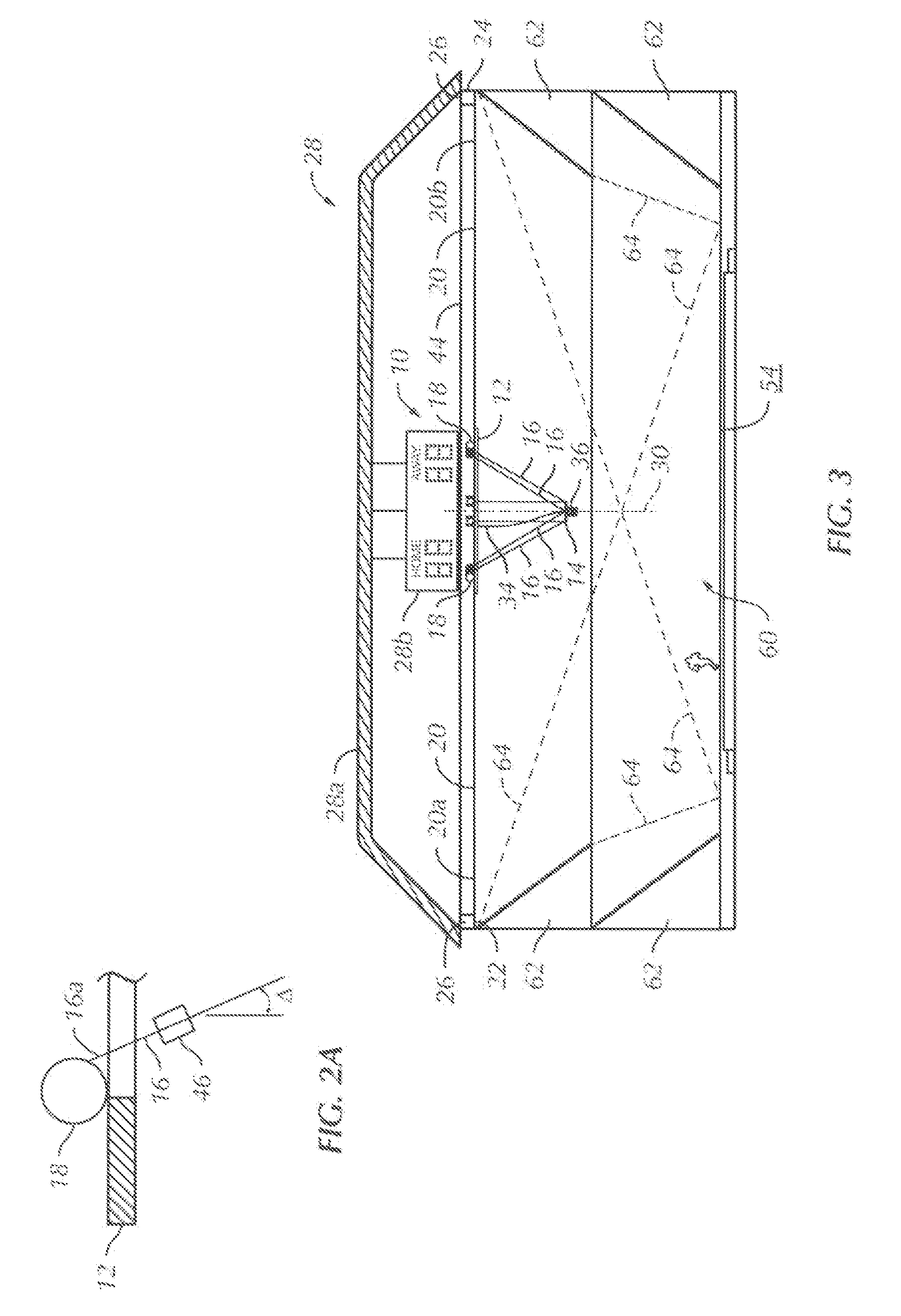
[0005] Briefly stated, the present invention is directed to an image capturing mechanism for capturing an image of a target. the image capturing mechanism includes a support platform, a camera platform suspended from the support platform by a support cable, a camera mounted to the camera platform and a stabilization mechanism associated with the camera. A first end of the support cable is mounted to the support platform and a second end of the support cable is mounted to the camera platform. The stabilization mechanism stabilizes the captured image or the camera.
[0009] In yet another aspect, the present invention is directed to an image capturing mechanism for capturing images of an observed area. The image capturing mechanism includes a support platform, a camera platform suspended from the support platform by at least one support cable, a stability mechanism associated with at least one support cable and the camera platform and a camera mounted to the camera platform. A first end of the at least one support cable mounted to the support platform and a second end of the at least one support cable mounted to the camera platform. The camera platform movable relative to the support platform and the stability mechanism stabilizing the camera platform and the camera relative to the observed area.

Problems solved by technology

Such prior art image capturing mechanisms are typically difficult to construct and employ, are often expensive and may provide a distraction or obstacle for observers at an event in specific types of settings.

Method used


Image

  • Aerial support structure and method for image capture
  • Aerial support structure and method for image capture
  • Aerial support structure and method for image capture

Examples


Embodiment Construction

[0022] Certain terminology is used in the following description for convenience only and is not limiting. The words “right”, “left”, “front”, “rear”, “lower”and “upper”designate direction in the drawings to which reference is made. The words “inwardly” and “outwardly” refer to directions toward and away from, respectively, the geometric center of the image capturing mechanism and designated parts thereof. Further, the words “up” and “down” refer to preferred orientations of the above-listed words, derivatives thereof and words of similar import.

[0023] Referring to the drawings in detail, wherein like numerals indicate like elements throughout, there are shown in FIGS. 1-8, first, second and third embodiments of an image capturing mechanism, generally designated 10, 10′, 10″, respectively, in accordance with the present invention. The image capturing mechanism 10, 10′, 10″ is generally utilized to capture images at a venue and to process the images. Like reference numerals are utili...


PUM


Abstract

An image capturing mechanism for capturing an image of a target includes a support platform, a camera platform suspended from the support platform by a support cable, a camera mounted to the camera platform and a stabilization mechanism associated with the camera. A first end of the support cable is mounted to the support platform and a second end of the support cable is mounted to the camera platform. The stabilization mechanism stabilizes the captured image of the camera. Methods for capturing images utilizing the image capturing mechanism and advertising that may be associated with the device are also disclosed. An advertising medium is mounted to the support platform or the camera platforms to provide noticeable advertising space in a venue where the image capturing mechanism is utilized.

Description

CROSS-REFERENCE TO RELATED APPLICATIONS [0001] This Patent Application claims priority to U.S. Provisional Patent Application No. 60 / 714,926, filed Sept. 7, 2005, entitled “Aerial Support Structure and Method for Image Capture” and U.S. Provisional Patent Application No. 60 / 757,757 filed Jan. 10, 2006, entitled “Aerial Support Structure for Camera”, each of which is incorporated herein by reference.BACKGROUND OF THE INVENTION [0002] The present invention is directed to an image capturing mechanism and a method for image capture. More particularly, the image capturing mechanism includes a camera platform suspended from a support platform wherein the camera platform is movable relative to the support platform. The image capturing mechanism is preferably, relatively lightweight and inexpensive to install and operate. The image capturing mechanism may be utilized to perform numerous tasks including capturing still images or photos or for capturing video images. the image capturing mecha...

Claims


Application Information

Patent Timeline
Patent Type & Authority Applications(United States)
IPC IPC(8): G03B21/00
CPCF16M11/18F16M11/42G03B17/56F16M2200/04G09F15/0081F16M11/046F16M11/425G09F7/22G03B17/561
Inventor GIEGERICH, GARYDOUGHERTY, EDMOND J.SIMMONS, GEORGE R. III
Owner WAVECAM MEDIA
Learn More