Optical pickup device and optical disk drive using the same

a pickup device and optical disk technology, applied in the manufacture of optical heads, instruments, data recording, etc., can solve the problems of cd light source optical efficiency falling, rim will become low, optical accuracy is increased, etc., and achieve the effect of stably carrying and sufficient accuracy

Inactive Publication Date: 2007-03-22
RICOH KK
View PDF33 Cites 3 Cited by
  • Summary
  • Abstract
  • Description
  • Claims
  • Application Information

AI Technical Summary

Benefits of technology

[0029] Another object of the present invention is to provide a light source unit package of an optical pickup device which is capable of optimizing the respective intensity distributions of the light beams from the plurality of light source without causing enlargement and high cost, and which stably receives the return light beam from the outside.
[0043] According to the optical disk drive of the present invention, it is possible to form the optimal light spot on the recording surface of each of the two kinds of optical disks by using the optical pickup device of the present invention. Therefore, the optical disk drive of the present invention responds to each of the two kinds of optical disks, and it is possible to stably carry out the high-speed access to each optical disk.

Problems solved by technology

However, if the optical system for 650 nm and the optical system for 780 nm are arranged individually in the optical pickup device, the problem that the size of the optical pickup device is enlarged arises.
If the optical pickup device is designed to raise the optical efficiency, the RIM will become low.
When the optical system is optimized to DVD, the optical efficiency of CD light source falls, and it is difficult to deal with improvement in the access speed for the optical disk.
On the other hand, when the optical system is optimized to CD, the problem arises that it is difficult to control accurately the diameter of a light spot on the recording surface of DVD.

Method used


Image

  • Optical pickup device and optical disk drive using the same
  • Optical pickup device and optical disk drive using the same
  • Optical pickup device and optical disk drive using the same

Examples


Embodiment Construction

[0109] A description will now be provided of the preferred embodiments of the present invention with reference to the accompanying drawings.

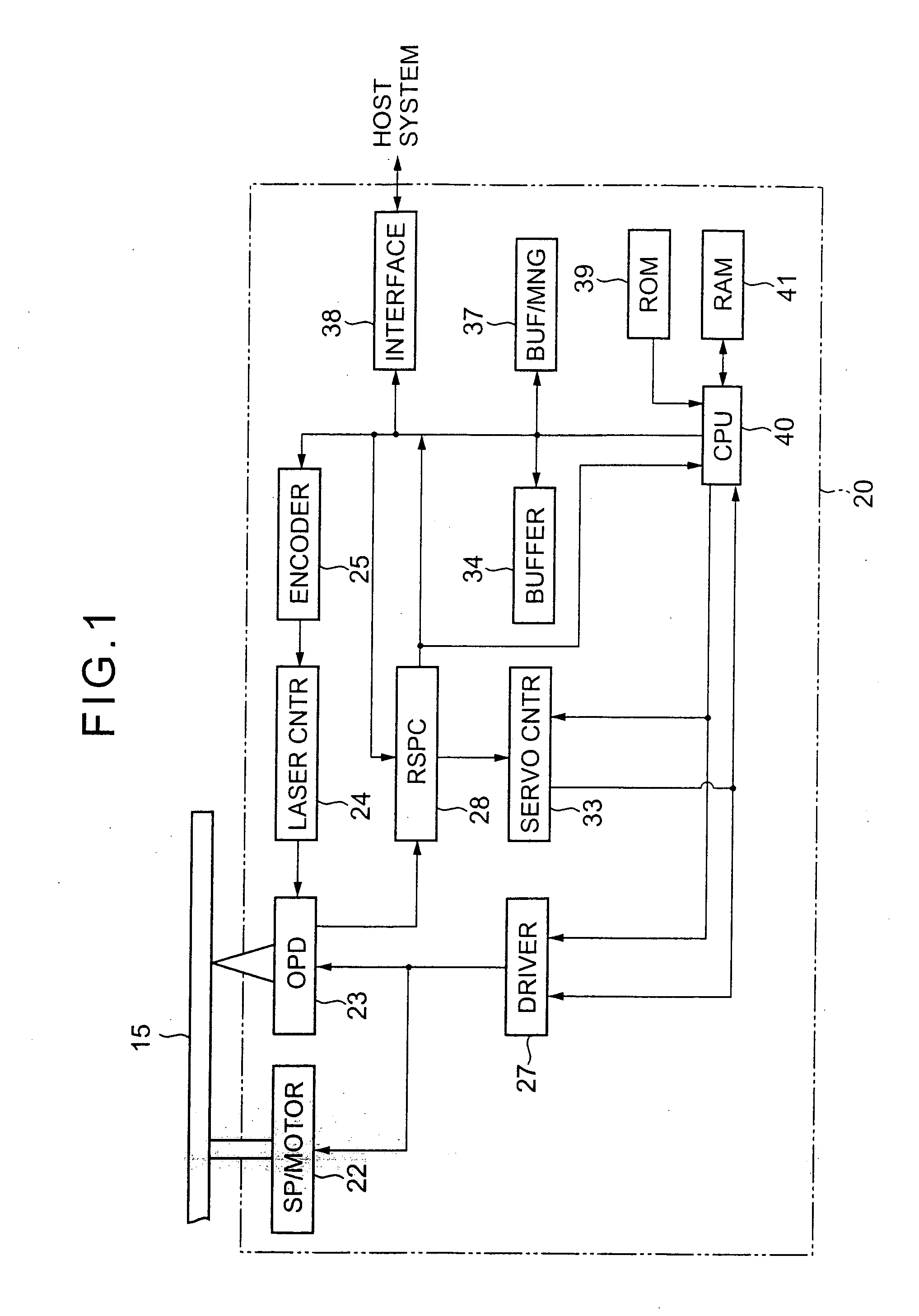
[0110]FIG. 1 shows the composition of an optical disk drive 20 in one preferred embodiment of the present invention in which the optical pickup device of the present invention is included.

[0111] The optical disk drive 20 shown in FIG. 1 comprises a spindle motor (SP / MOTOR) 22 for carrying out a rotation drive of the optical disk 15, an optical pickup device (OPD) 23, a laser control circuit (LASER CNTR) 24, an encoder (ENCODER) 25, a motor driver (DRIVER) 27, a reproduction signal processing circuit (RSPC) 28, a servo controller (SERVO CNTR) 33, a buffer RAM (BUFFER) 34, a buffer manager (BUF / MNG) 37, an interface (INTERFACE) 38, a ROM 39, a CPU 40, and a RAM 41.

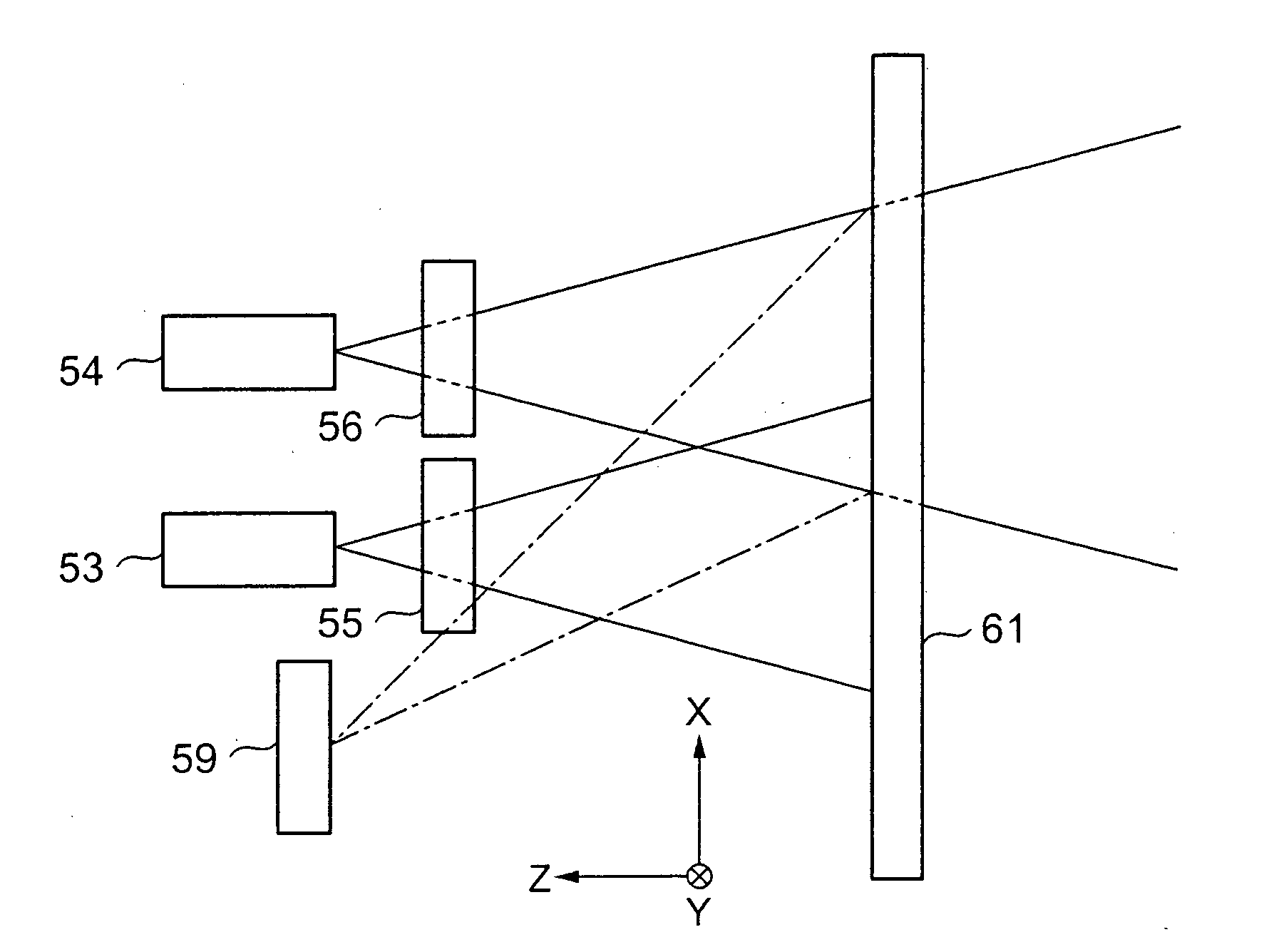
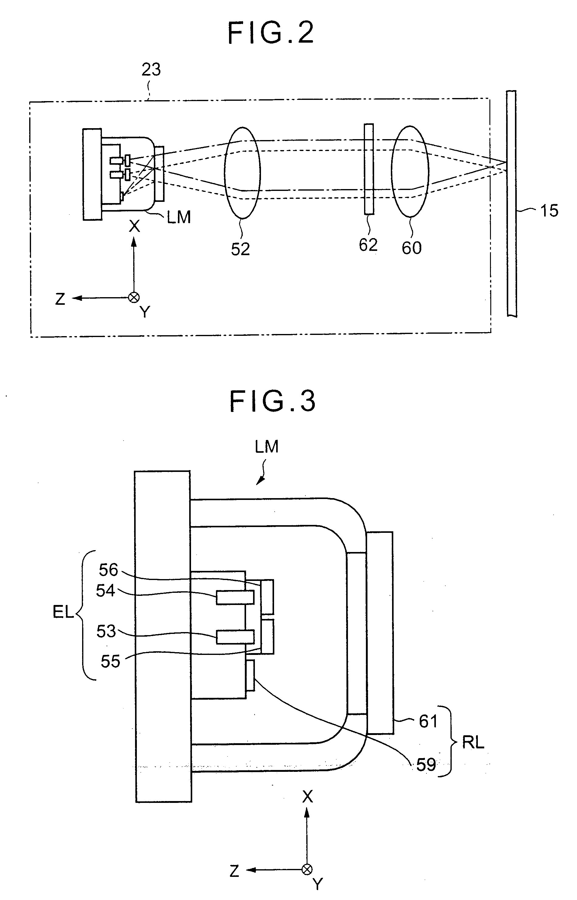
[0112] The optical pickup device 23 is provided for receiving the return light from the recording surface of the optical disk 15, and for emitting laser light to the recording surface...


PUM

PropertyMeasurementUnit
wavelengthaaaaaaaaaa
sizeaaaaaaaaaa

Abstract

An optical pickup device includes a light source unit an optical system which leads a return light beam to a predetermined light-receiving location and includes an object lens focusing each light beam from the light source unit to a recording surface of a corresponding storage medium and a photodetector arranged at the light-receiving location. The light source unit includes a plurality of light sources outputting light beams respectively, the plurality of light sources being arranged in proximity to each other, and a divergence-angle changing unit changing an angle of divergence of a light beam output from at least one of the plurality of light sources.

Description

BACKGROUND OF THE INVENTION [0001] 1. Field of the Invention [0002] The present invention relates to an optical pickup device and an optical disk drive using the same. More specifically, the present invention relates to an optical pickup device for an optical disk drive which focuses a light beam to a corresponding one of two optical disks of different types for recording of information, and receives a reflected light beam from the corresponding optical disk for reproduction of information. [0003] 2. Description of the Related Art [0004] In the optical disk drive, storage media, such as optical disks, in which tracks in the spiral or concentric formation are formed in the recording surface of the optical disk, are used for recording and reproduction of information. The optical disk drive emits a light beam to the optical disk to record information in the recording surface of the optical disk, and receives a reflected light beam from the recording surface of the optical disk to repro...

Claims


Application Information

Patent Timeline
Patent Type & Authority Applications(United States)
IPC IPC(8): G11B7/135G11B7/00G11B7/12G11B7/125G11B7/22
CPCG11B7/1205G11B7/1275G11B7/1353G11B7/1356G11B2007/0006G11B7/1369G11B7/1378G11B7/1398G11B7/22G11B7/1359G11B7/123
Inventor OGATA, TETSUYA
Owner RICOH KK
Why Eureka
Try Eureka