
Method of constructing a pile foundation

Active Publication Date: 2007-03-22
SO L E S SOC LAVORI EDILI E SERBATOI
View PDF6 Cites 22 Cited by
  • Summary
  • Abstract
  • Description
  • Claims
  • Application Information

AI Technical Summary

Benefits of technology

[0005] It is an object of the present invention to provide a method of constructing a pile foundation, designed to eliminate the aforementioned drawbacks, and which, at the same time, is cheap and easy to implement.
[0006] It is a further object of the present invention to provide a pile for constructing a pile foundation, designed to eliminate the aforementioned drawbacks, and which, at the same time, is cheap and easy to build.

Problems solved by technology

The transverse dimensions of the head, however, are limited by those of the hole, which, over and above a given size, seriously impairs the capacity of the foundation structure, and makes it difficult to fix the sunk pile axially to the foundation structure.

Method used


Image

  • Method of constructing a pile foundation
  • Method of constructing a pile foundation
  • Method of constructing a pile foundation

Examples


Embodiment Construction

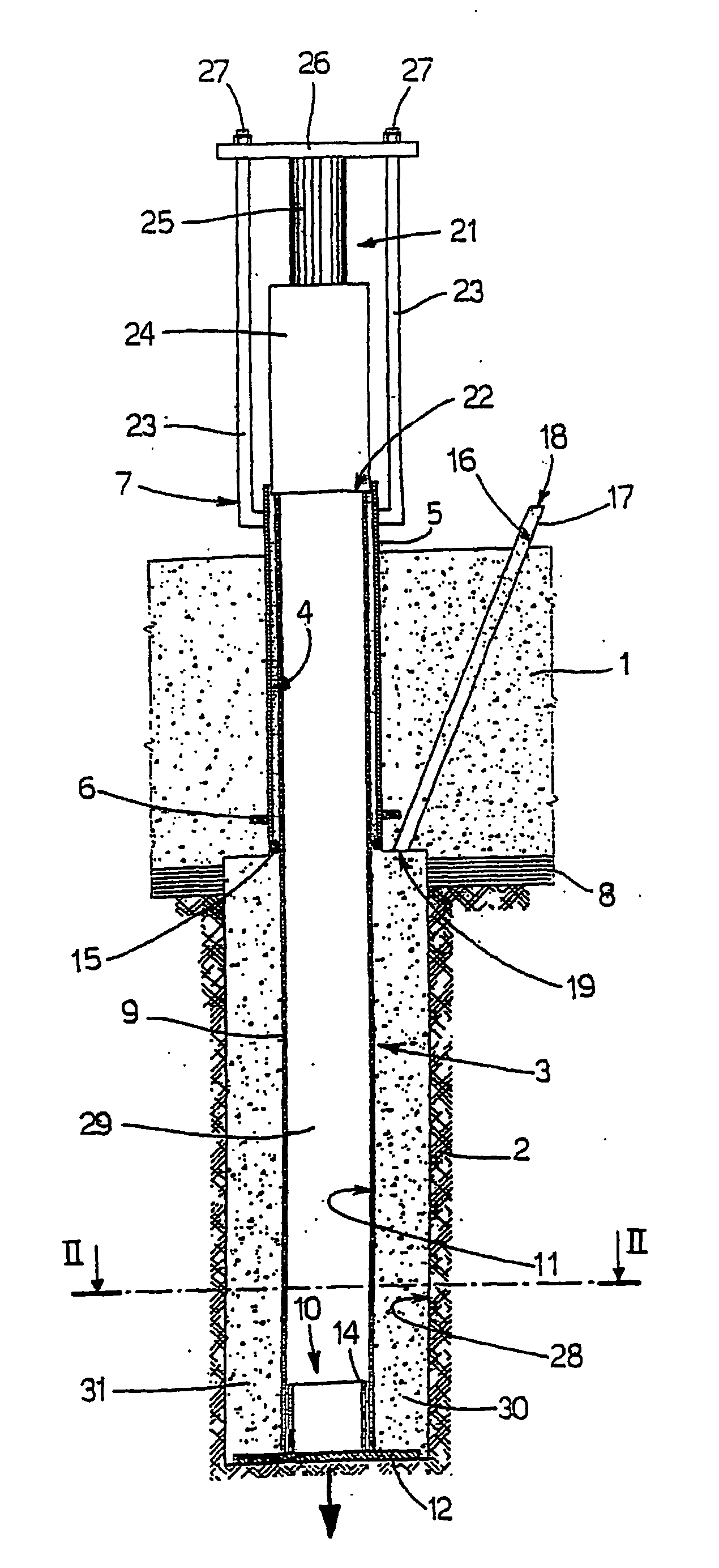
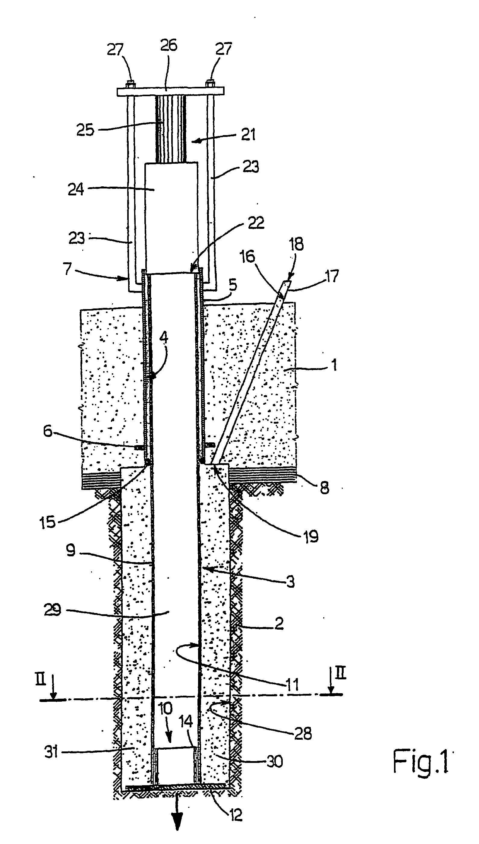
[0025] Number 1 in FIG. 1 indicates a foundation structure of a building (not shown), which is built on the ground 2 and is normally defined by a continuous beam, a slab, or reinforced concrete footings. Foundation structure 1 may obviously be used for a building, for any other type of building structure (e.g. a bridge), and more generally for any structure requiring a ground foundation (e.g. a hydraulic turbine, industrial boiler, or electric pylons).

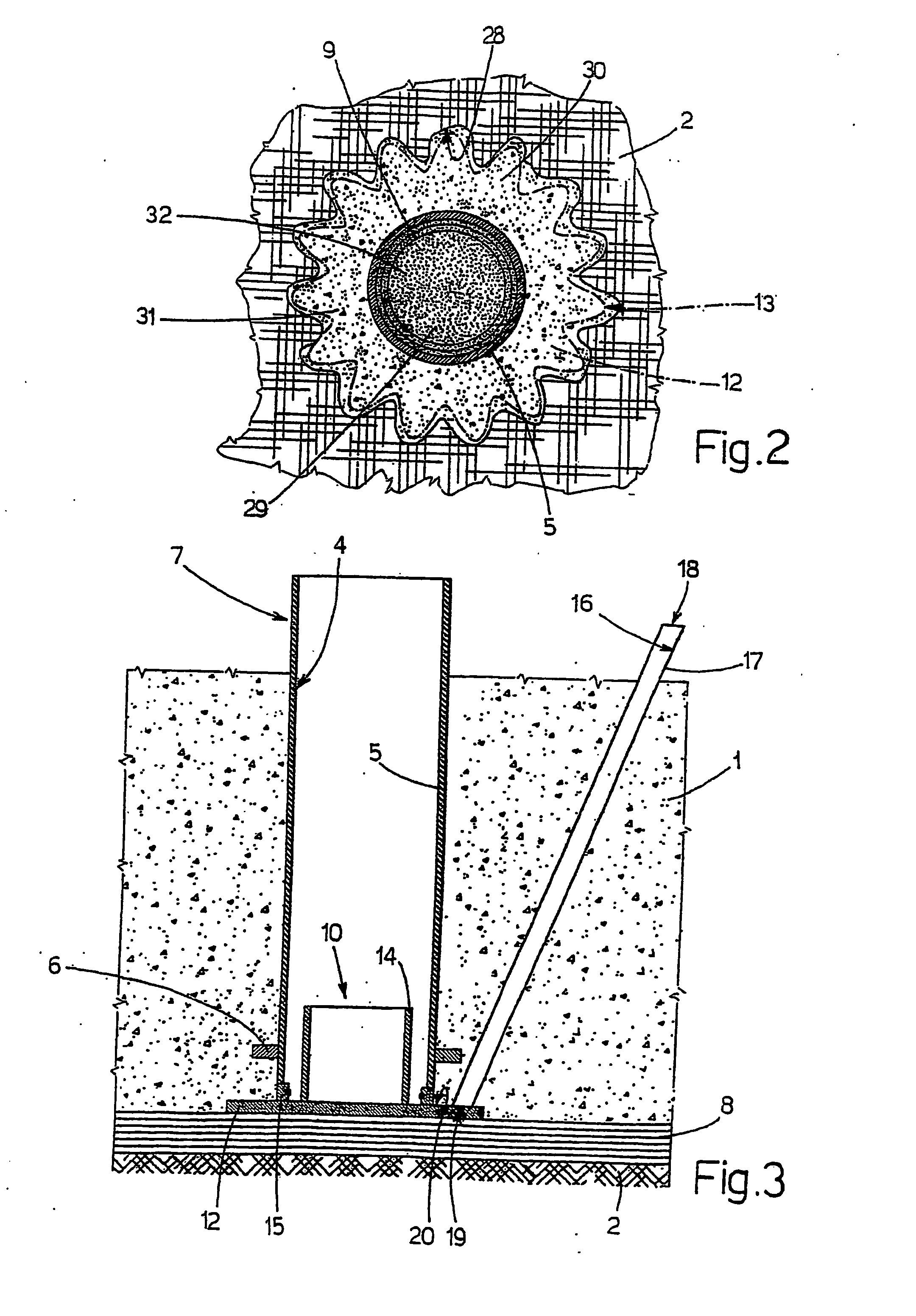
[0026] Foundation structure 1 is normally buried, and transfers the loads on it to ground 2 by means of a number of piles 3 (only one shown) extending through and downwards from the structure. For which purpose, for each pile 3, structure 1 comprises a substantially vertical hole 4, of cylindrical or other shaped cross section, and lined with a metal pipe 5, which is fixed to foundation structure 1 by a ring 6 incorporated in structure 1, and projects upwards from foundation structure 1 by a top portion 7. A layer 8 of relatively poor...


PUM


Abstract

A method of constructing a pile foundation, wherein a foundation structure is built on the ground, and has at least one through hole, and a connecting member fixed to the foundation structure, adjacent to the hole, and having at least one portion projecting upwards; a pile is inserted through the hole; and a number of thrusts are applied statically on the pile, to drive the pile into the ground, by means of a thrust device, which is located over the pile, cooperates with a top end of the pile, and is connected to the projecting portion of the connecting member which, when driving the pile, acts as a reaction member for the thrust device.

Description

TECHNICAL FIELD [0001] The present invention relates to a method of constructing a pile foundation, in particular of a building. BACKGROUND ART [0002] A pile foundation of a building is constructed by building a ground foundation structure of the building, having at least one through hole and fitted through, adjacent to the hole, with at least two cables fixed to the structure and projecting upwards. Once the foundation structure is completed, a metal pile is inserted through the hole and subjected to a series of static thrusts to drive it into the ground; and, once driven, the top of the pile is fixed axially to the foundation structure. Each thrust is applied by a thrust device, which is set up on top of the pile, cooperates with the top end of the pile, and is connected to the projecting portions of the cables, which, when driving the pile, act as reaction members for the thrust device. [0003] The pile comprises a constant-section rod; and a wide bottom head, which is connected i...

Claims


Application Information

Patent Timeline
IPC IPC(8): E02D13/00E02D5/28E02D5/48E02D5/52E02D27/12E02D27/48
CPCE02D5/28E02D5/48E02D27/48E02D27/12E02D5/523
Inventor COLLINA, VINCENZOZAGO, ROBERTOZAMBIANCHI, LAMBERTO
Owner SO L E S SOC LAVORI EDILI E SERBATOI
Learn More