Method of determining opening of an internal combustion engine intake valve

a technology of internal combustion engine and intake valve, which is applied in the direction of machines/engines, non-mechanical valves, instruments, etc., can solve the problems of inability to guarantee mechanically the opening of the intake valve by the camshaft, the inability to control the position of one or more intake valves, and the inability to manufacture and manufacture a single intake valve. the solution is not easy to achieve, and the cost of insulate the position is high

Active Publication Date: 2011-07-14
MARELLI EURO SPA
View PDF3 Cites 15 Cited by
  • Summary
  • Abstract
  • Description
  • Claims
  • Application Information

AI Technical Summary

Benefits of technology

[0009]It is an object of the present invention to provide a method of determining opening of an internal combustion engine intake valve, designed to eliminate the above drawbacks, and which, in particular, is cheap and easy to implement.

Problems solved by technology

In the event of a malfunction in the hydraulic circuit of the valve opening control device hydraulic actuators, or in a hydraulic actuator or solenoid valve of the control device, the position of one or more intake valves may not be controlled correctly (typically, the intake valve may not open).
In other words, opening of the intake valves is not guaranteed mechanically by the camshaft, because of the hydraulic actuators between the camshaft and the intake valve stems.
Which means that a malfunction in the hydraulic actuators or the control / power chain of the hydraulic actuators may prevent the intake valves from opening correctly.
This solution, however, involves considerable cost, not only in terms of purchase, installation and wiring, but also to insulate the position sensors to withstand the high temperatures generated in the cylinder head area of an internal combustion engine.

Method used


Image

  • Method of determining opening of an internal combustion engine intake valve
  • Method of determining opening of an internal combustion engine intake valve
  • Method of determining opening of an internal combustion engine intake valve

Examples


Embodiment Construction

[0009]It is an object of the present invention to provide a method of determining opening of an internal combustion engine intake valve, designed to eliminate the above drawbacks, and which, in particular, is cheap and easy to implement.

[0010]According to the present invention, there is provided a method of determining opening of an internal combustion engine intake valve, as claimed in the attached Claims.

BRIEF DESCRIPTION OF THE DRAWINGS

[0011]A non-limiting embodiment of the present invention will be described by way of example with reference to the accompanying drawings, in which :

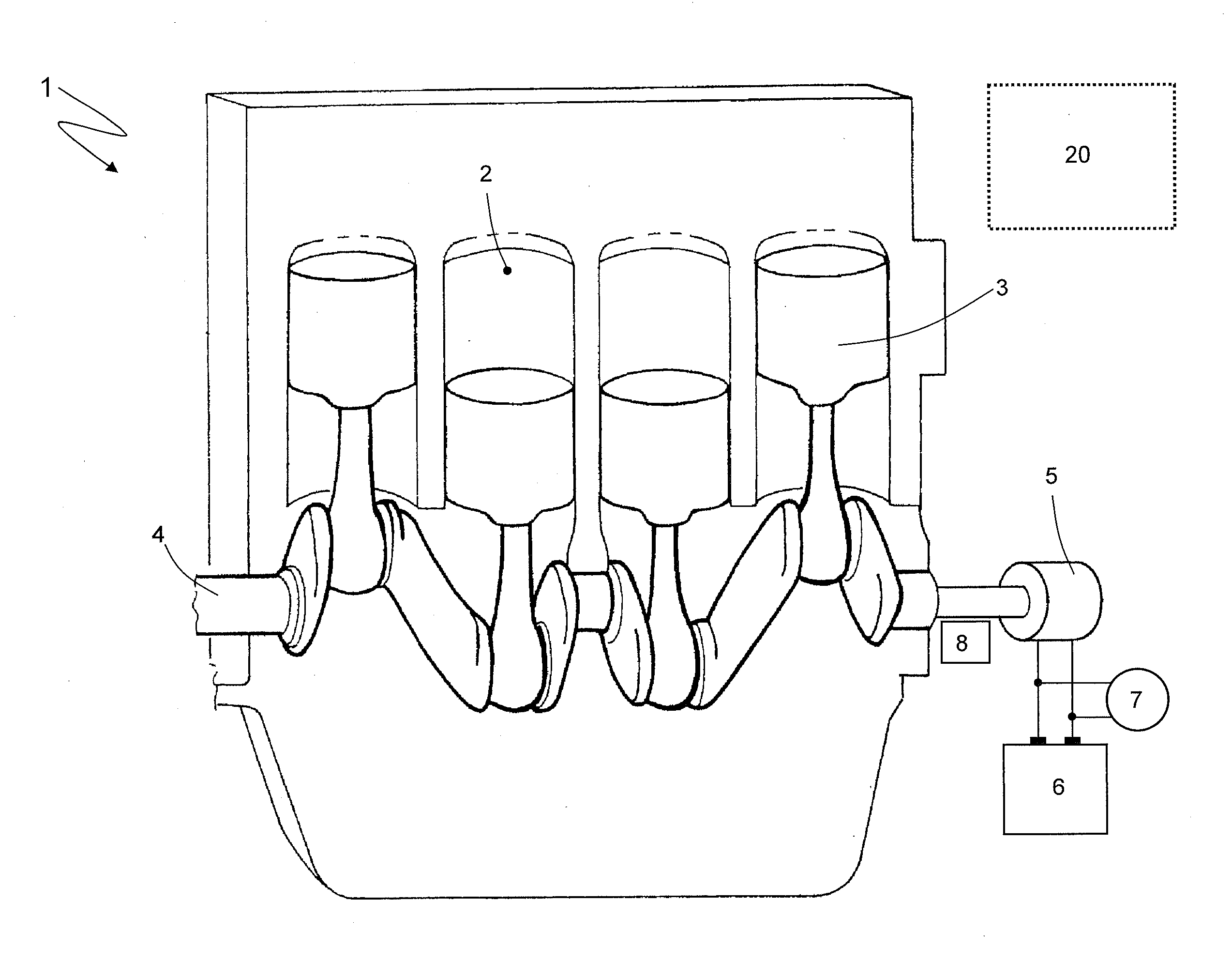
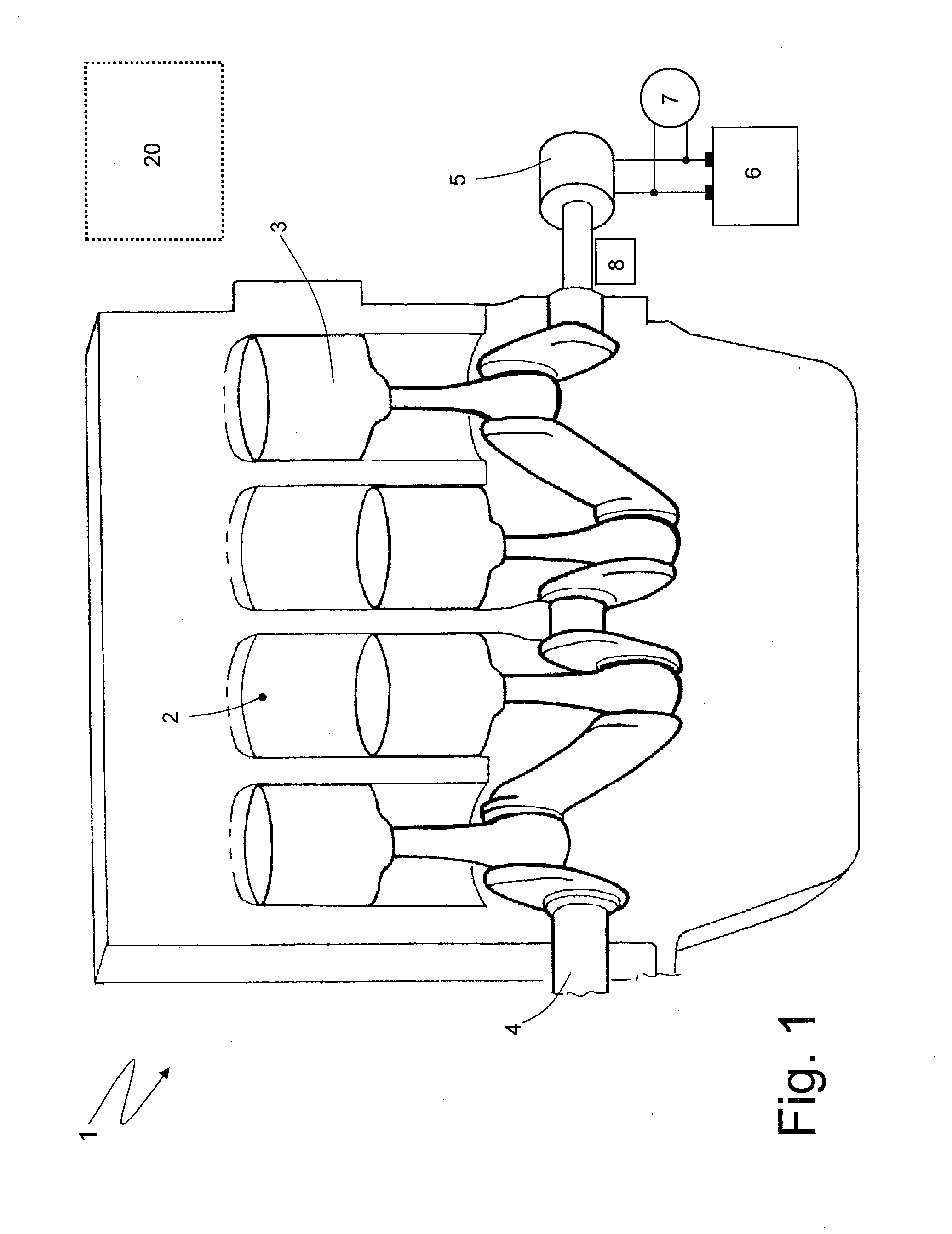
[0012]FIG. 1 shows a schematic of an internal combustion engine featuring a control unit implementing the method of determining opening of an internal combustion engine intake valve according to the present invention;

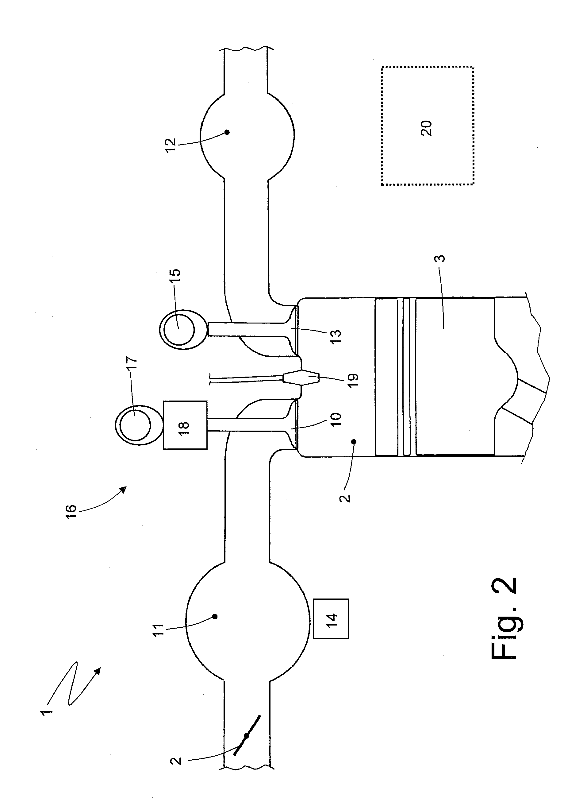
[0013]FIG. 2 shows a schematic of a cylinder of the FIG. 1 internal combustion engine;

[0014]FIGS. 3-6 show time graphs of physical quantities of the FIG. 1 internal combustion engine, used ...


PUM


Abstract

A method of determining opening of an intake valve of an internal combustion engine, the method including the steps of: determining the time pattern of an intake pressure in an intake manifold of the internal combustion engine, the time pattern of the rotation speed of a drive shaft of the internal combustion engine, or the time pattern of a voltage at the terminals of a battery of the internal combustion engine; determining an intake-frequency component of the intake pressure, the rotation speed, or the voltage; anddetermining opening of the intake valve as a function of the intake-frequency component of the intake pressure, and also as a function of the intake-frequency component of the rotation speed or voltage.

Description

CROSS-REFERENCE TO RELATED APPLICATION[0001]This application claims priority under 35 U.S.C. §119 to Italian Patent Application No. B02009A-000599, filed on Sep. 21, 2009 with the Italian Patent and Trademark Office, the disclosure of which is incorporated herein in its entirety by reference.TECHNICAL FIELD[0002]The present invention relates to a method of determining opening of an internal combustion engine intake valve.BACKGROUND ART[0003]An internal combustion engine comprises at least one cylinder, in which a piston, connected mechanically to a drive shaft, moves back and forth. The cylinder is connected to an intake manifold by at least one intake valve, and to an exhaust manifold by at least one exhaust valve. And the position of the intake and exhaust valves of a conventional internal combustion engine is controlled directly by one or two camshafts powered by the drive shaft.[0004]A new type of internal combustion engine (known commercially as “Multi-Air”) has recently been p...

Claims


Application Information

Patent Timeline
Patent Type & Authority Applications(United States)
IPC IPC(8): G01M15/04
CPCF01L2001/0537F01L2800/01F01L2800/12Y02T10/18F02D13/0223F01L1/143F01L9/025F01L2820/043Y02T10/12F01L9/14
Inventor ZANOTTI, MASSIMOSENSI, FABIOPANCIROLI, MARCOLEONI, ANDREAALUNNI, FRANCESCOCAVANNA, FILIPPO
Owner MARELLI EURO SPA
Why Eureka
Try Eureka