Inkjet image forming apparatus and method of compensating for defective nozzle

Inactive Publication Date: 2007-03-29
S PRINTING SOLUTION CO LTD
View PDF5 Cites 2 Cited by
  • Summary
  • Abstract
  • Description
  • Claims
  • Application Information

AI Technical Summary

Benefits of technology

[0011] Embodiments of the present invention substantially solve the above and other problems, and provide an inkjet image forming apparatus and a method of compensating for a defective nozzle capable of improving image quality by compensating for the defective nozzle.
[0012] Embodiments of the present invention also provide an inkjet image forming apparatus and a method of compensating for a defective nozzle capable of minimizing influence of a defective nozzle on image quality by overcoming limitations of conventional compensating methods wherein only black colors can be compensated.
[0013] Embodiments of the present invention also provide an inkjet image forming apparatus and a method of compensating for a defective nozzle capable of prolonging the life time of a print head.

Problems solved by technology

Since the white bands of an image printed on the printing medium can be easily seen, the white bands severely affect printing quality.
However, the method cannot be used for a case where nozzles firing other color ink (that is, other than black ink) have a defect.
In addition, in a case where any one of the nozzles used for compensation also has a defect, the compensation is performed with resulting colors such as red (yellow+magenta), green (cyan+yellow), and blue (cyan+magenta), that are different from the process Black, and severe detrimental effects on the print quality can result.

Method used


Image

  • Inkjet image forming apparatus and method of compensating for defective nozzle
  • Inkjet image forming apparatus and method of compensating for defective nozzle
  • Inkjet image forming apparatus and method of compensating for defective nozzle

Examples


Embodiment Construction

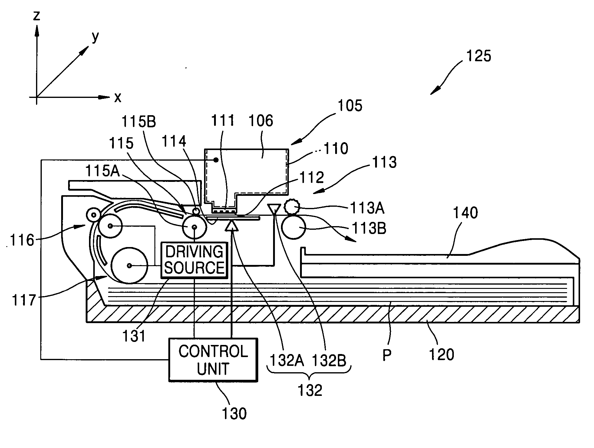
[0045] Now, an exemplary inkjet image forming apparatus and a method of compensating for a defective nozzle in the inkjet image forming apparatus according to embodiments of the present invention will be described in detail with reference to the accompanying drawings. For better understanding of the following description, a complete construction of an inkjet image forming apparatus will be first described, and an exemplary method of compensating for the defective nozzle in the inkjet image forming apparatus will then be described. In the drawings, the thicknesses of layers and regions are exaggerated for clarity. Meanings of terminology used herein should be determined in consideration of functionality of embodiments of the present invention, and may be variable depending on user's or operator's intention, or customs known to those skilled in the art. Therefore, corresponding meanings should be determined with reference to the entire specification. Like reference numerals in the dra...


PUM


Abstract

An inkjet image forming apparatus and method of compensating for a defective nozzle in an inkjet image forming apparatus are provided. By analyzing firing states of nozzles firing ink at a compensated position, which is a position printed with the defective nozzle, and at positions adjacent to the compensated position, and by firing ink having a color different from that of the defective nozzle at the compensated position according to the firing states of the nozzles to diffuse the ink fired at the adjacent positions into the compensated position, the defective nozzle is compensated. Accordingly, the missing dot of the defective nozzle is compensated for, so that it is possible to prevent deterioration in image quality such as a white band which can be easily perceived by a user. In addition, by adjusting a firing amount or chroma of the ink fired at the compensated position or the adjacent positions, it is possible to improve a compensation effect.

Description

CROSS-REFERENCE TO RELATED PATENT APPLICATION [0001] This application claims the benefit under 35 U.S.C. § 119(a) of Korean Patent Application No. 10-2005-0090708, filed in the Korean Intellectual Property Office on Sep. 28, 2005, the entire disclosure of which is incorporated herein by reference. BACKGROUND OF THE INVENTION [0002] 1. Field of the Invention [0003] The present invention relates to an inkjet image forming apparatus. More particularly, the present invention relates to an inkjet image forming apparatus capable of compensating for deterioration in image quality caused by the occurrence of a defective nozzle, and a method of compensating for the defective nozzle occurrence in the inkjet image forming apparatus. [0004] 2. Description of Related Art [0005] In general, inkjet image forming apparatuses are apparatus for forming an image by firing ink with a print head which is separated by a predetermined interval from a printing medium and which reciprocates in a direction p...

Claims


Application Information

Patent Timeline
IPC IPC(8): B41J29/38
CPCB41J29/393B41J2/2139B41J2/0451B41J2/21B41J2/16585
Inventor VLADISLAV, TEREKHOV
Owner S PRINTING SOLUTION CO LTD
Why Eureka
Try Eureka