Transport method and apparatus for mower deck
Active Publication Date: 2007-04-05
DEERE & CO
12 Cites 12 Cited by
AI-Extracted Technical Summary
Problems solved by technology
A mower deck may be cumbersome to lift and move after it is disconnected from its mounting position under the tract...
Abstract
Transport brackets are welded onto the top surface of the mower deck, each transport bracket having vertical plates with holes extending transversely through the plates. Pins extend through at least one hole in the plates and are secured to a rear mounted hitch of a tractor. The mower deck may be lifted and transported in a raised position behind the tractor, and also may be pivoted to a position for servicing.
Application Domain
Mowers
Technology Topic
MowerEngineering +1
Image
Examples
- Experimental program(1)
Example
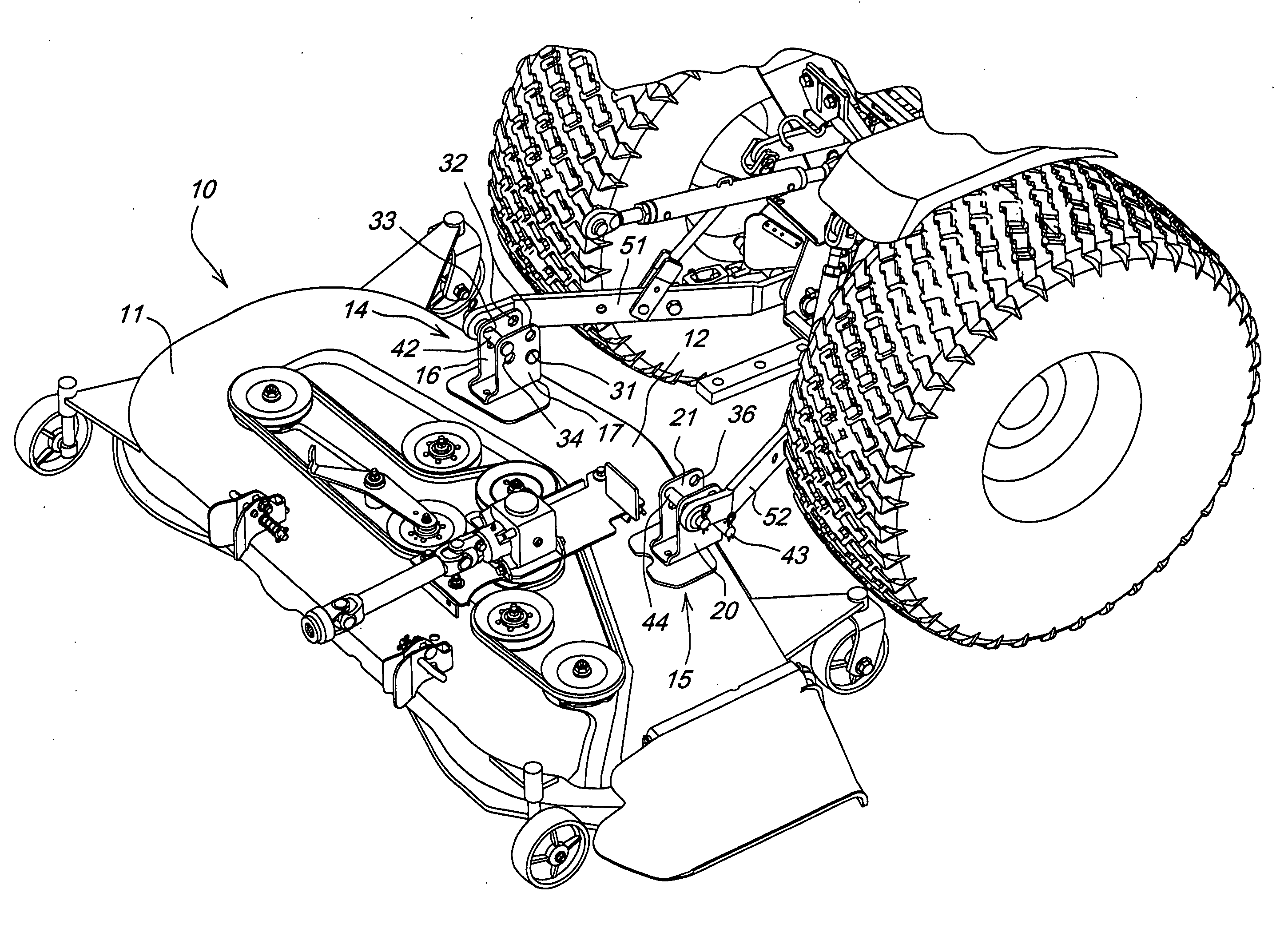
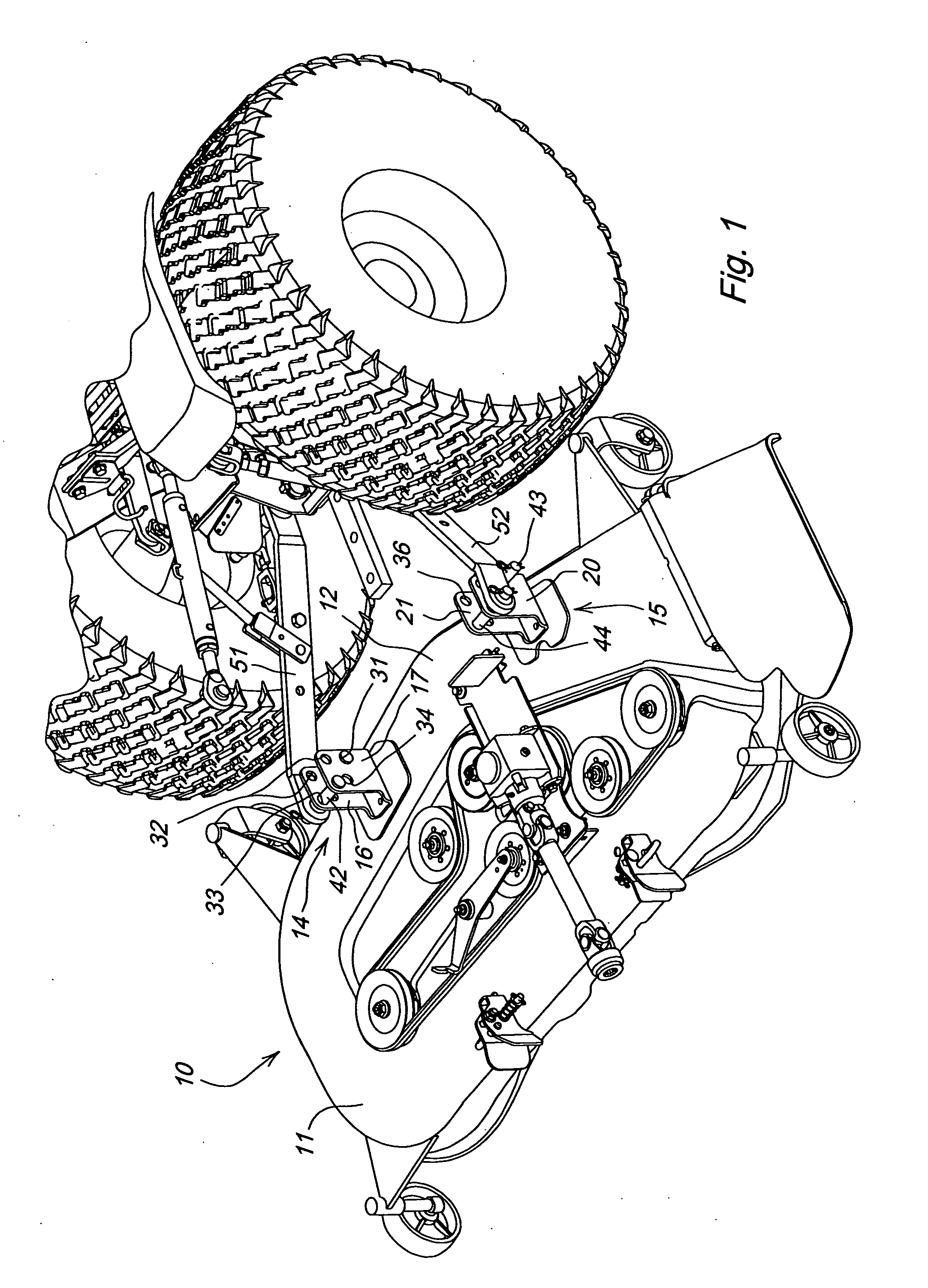
[0011] In one embodiment, as shown in FIG. 1, mower deck 10 may cover a plurality of rotary cutting blades mounted on the lower ends of vertically oriented spindles. The mower deck may have a top surface 11, a front facing edge 12 with a rim extending downwardly from the top surface, left and right sides and a back edge. During mowing, the mower deck may be mid-mounted under a tractor or vehicle frame between the tractor or other vehicle's front and rear wheels.
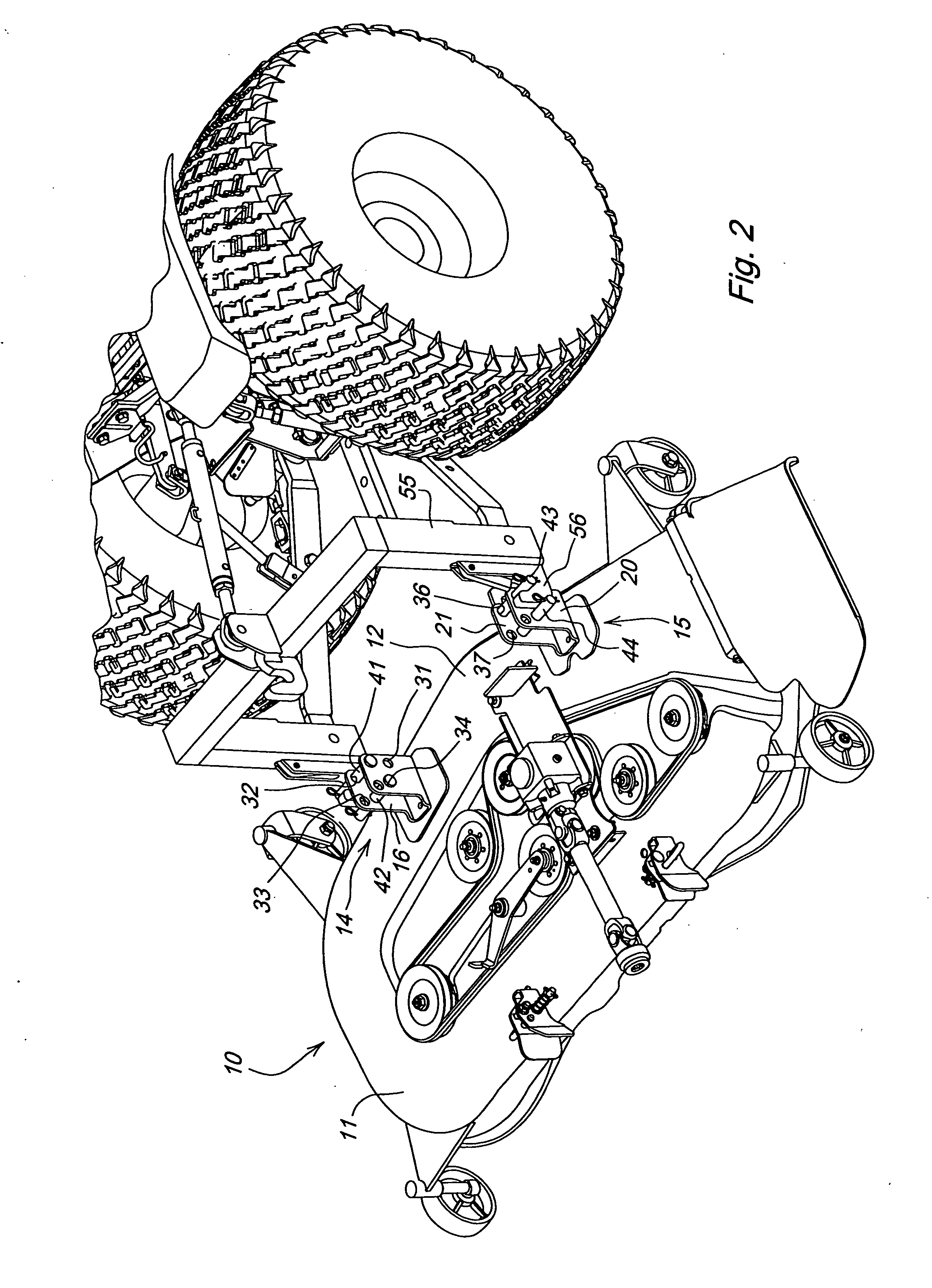
[0012] In one embodiment, left and right transport brackets 14, 15 may be mounted on the top surface of the mower deck. The left and right transport brackets may be welded or attached by mechanical means to the top surface of the deck, near either the front rim or rear rim of the deck. In the embodiment of FIGS. 1 and 2, the transport brackets are adjacent the mower deck's front rim. The spacing between the left transport bracket and the right transport bracket may correspond to the standard width of a three point hitch or a similar rear mounted quick attach coupler conventionally mounted to the rear of a tractor that may be used to raise and lower attachments using hydraulic power.
[0013] In one embodiment, left transport bracket 14 may include a pair of vertical plates 16, 17 fastened by welds or other secure mechanical attachment means to the top surface of the mower deck. Plates 16, 17 may be separated from each other by between about one inch and about five inches, and the brackets together may form a one-piece U-shaped member.
[0014] Now referring to FIG. 3, both plates 16, 17 may have a plurality of holes transverse to the plate's vertical alignment. For example, each plate 16, 17 may have four holes 31, 32, 33, 34. One or more pins may be inserted through the holes so that each pin may extend between plates 16, 17. For example, front pin 41 may be inserted through either the lower front hole 31 or upper front hole 32 in each of the two plates, and rear pin 42 may be inserted through either the upper rear hole 33 or the lower rear hole 34 in each of the two plates, so that each pin 41, 42 extends between the two plates 16, 17.
[0015] Similarly, in one embodiment, right transport bracket 15 may include a pair of vertical plates 20, 21 fastened by welds or other secure attachment to the top surface of the mower deck. Plates 20, 21 may be separated from each other by between about one inch and about five inches, and the brackets together may form a one-piece U-shaped member.
[0016] In one embodiment, both plates 20, 21 may have a plurality of holes transverse to the plate's vertical alignment. For example, each plate 20, 21 may have four holes 35, 36, 37, 38. One or more pins may be inserted through the holes so that each pin extends between plates 20, 21. For example, front pin 43 may be inserted through either the lower front hole 35 or upper front hole 36 in each of the two plates, and rear pin 44 may be inserted through either the upper rear hole 37 or lower rear hole 38 in each of the two plates, so that each pin extends between plates 20, 21.
[0017] In one embodiment, to lift and carry the mower deck in a generally horizontal position using a three point hitch, front pins 41, 43 may be inserted into the lower front holes 31, 35 in both transport bracket plates, and rear pins 42, 44 may be inserted into the upper rear holes 33, 37. The front and rear pins may maintain the mower deck in a first position within about 10 degrees from horizontal and keep the deck from pivoting. This is because front pins 41, 43 may abut and rest against the bottom of lower lift links 51, 52, while rear pins 42, 44 may fasten to the lower lift links as the pins are inserted through a ball 54 adjacent the ends of each lower lift link of the three point hitch. The present invention allows the mower deck to be lifted and carried in a generally horizontal position by a rear mounted three point hitch, without using the center link of the hitch.
[0018] In one embodiment, to lift and carry a mower deck in a generally horizontal position with a quick attach coupler 55 mounted to a three point hitch, as shown in FIG. 2, front pins 41, 43 may be inserted into the top front holes 32, 36, and rear pins 42, 44 may be inserted into the lower rear holes 34, 38. Front pins 41, 43 may be used to secure the deck to the hitch hooks 56, while rear pins 42, 44 may be used to keep the deck from rotating because the pins rest against the backside of the hitch hook 56.
[0019] In one embodiment, each of the pins may be secured or locked in position when they are used to lift and carry a mower deck, and also when the mower deck is being used. For example, each pin may have several holes through which a retainer 61 may be inserted to to secure the pins into one or more desired positions. For example, in one embodiment, the pins may be locked in a first position extending toward the outside of the mower deck when the mower deck is being transported. Additionally, the pins may be be locked in a second position extending inwardly toward the inside of the mower deck. Placing the pins in the second position may help prevent the pins from interfering with a drive-over path on the top surface of the mower deck.
[0020] In one embodiment, if a three point hitch is used to lift the mower deck, the deck may be moved to a second or service position within about 10 degrees from vertical by removing the front pins. Similarly, if a quick attach coupler is used to lift the mower deck, the deck may be moved to a second or service position within about 10 degrees of vertical by removing the rear pins. Thus, the mower deck may quickly and easily swing from a first postion to a second position for servicing.
[0021] In an alternative embodiment, a single pin may be used in each of the left and right brackets, instead of a pair of pins in each of the brackets. The mower deck may be lifted by engaging a three point hitch or quick attach coupler to the single pin extending between the plates in each bracket. To keep the mower deck generally horizontal when it is lifted, the top surface of the mower deck may abut and rest against the underside of the three point hitch or quick attach coupler. This may require reinforcing the top surface of the mower deck substantially so that it may engage the underside of the hitch or coupler without deforming or becoming damaged.
[0022] In one embodiment, a method for transporting the mower deck includes the following steps. First, a tractor may be positioned less than about two feet in front of mower deck 10. Pins on the left and right transport brackets may be inserted through the holes that are specified for the three point hitch or other rear-mounted hitch. As stated above, pin placement depends on the type of hitch being used. The pins may may be locked in place with retainers. The hitch hooks then may be lowered sufficiently to engage the top pins on both the left and right transport brakets. As shown in FIG. 5, as the deck is raised off the ground, the lower pins 43 in the transport bracket prevent the deck from pivoting. The raised deck then may be safely transported.
[0023] The method and apparatus described may be used to lift a mower deck off the ground surface behind a tractor to a height of several inches up to about four feet. The transport brackets mounted on the top surface of the mower deck allow transporting the deck behind a tractor using a three point hitch or other rear-mounted hitch. Additionally, the transport brackets allow the mower deck to be lifted and tilted so that the underside of the mower deck may be accessed and serviced.
[0024] Having described the preferred embodiment, it will become apparent that various modifications can be made without departing from the scope of the invention as defined in the accompanying claims.
ASSIGNMENT
[0025] The entire right, title and interest in and to this application and all subject matter disclosed and/or claimed therein, including any and all divisions, continuations, reissues, etc., thereof are, effective as of the date of execution of this application, assigned, transferred, sold and set over by the applicant(s) named herein to Deere & Company, a Delaware corporation having offices at Moline, Ill. 61265, U.S.A., together with all rights to file, and to claim priorities in connection with, corresponding patent applications in any and all foreign countries in the name of Deere & Company or otherwise.
PUM


Description & Claims & Application Information
We can also present the details of the Description, Claims and Application information to help users get a comprehensive understanding of the technical details of the patent, such as background art, summary of invention, brief description of drawings, description of embodiments, and other original content. On the other hand, users can also determine the specific scope of protection of the technology through the list of claims; as well as understand the changes in the life cycle of the technology with the presentation of the patent timeline. Login to view more.