Synchronous drive for split sickle bars on harvester header

a harvester and header technology, applied in the direction of mowers, agriculture tools and machines, agriculture, etc., can solve the problems of reducing the life of the machine, and achieve the effect of less vibration, less vibration and wear and tear of the harvester

Active Publication Date: 2010-02-09
BJ SERVICES CO +1
View PDF24 Cites 38 Cited by
  • Summary
  • Abstract
  • Description
  • Claims
  • Application Information

AI Technical Summary

Benefits of technology

[0011]By keeping the two sickle bar sections in synchronicity, there is less vibration at the reciprocating drives, and less wear and tear on the drive train as well as less harvester vibration and wear and tear. Further, there is improved cutting where the sickle bar sections overlap at or near the center of the header, so that there is a true cut of the crop rather than pulling and tearing. Balanced sickle bar sections loads permit higher operating rpm, and higher sickle speeds, which allow faster harvester ground speed. The harvester may be a combine as shown, a swather, a mower-conditioner or the like, with a long cutter bar and two sickle sections.

Problems solved by technology

However, due to the normal internal leakage of the motors, the second motor in the series connection (the slave motor) will rotate at different rpm from the first or master motor.
Small differentials in speed will cause the sickle bar sections to go in and out of “timing” or synchronization and strip the crop, rather than cut it, and also cause vibration.
The overlapping center sections of the two sickle bar sections will be in a position where the crop is torn or stripped, rather than cut, for short intervals of time, so while the cutting in not ideal, the tearing of the crops is intermittent, rather that for long periods of time.
The vibrations can be felt by the operator, and the vibrations also reduce the life of the machine.

Method used


Image

  • Synchronous drive for split sickle bars on harvester header
  • Synchronous drive for split sickle bars on harvester header
  • Synchronous drive for split sickle bars on harvester header

Examples


Embodiment Construction

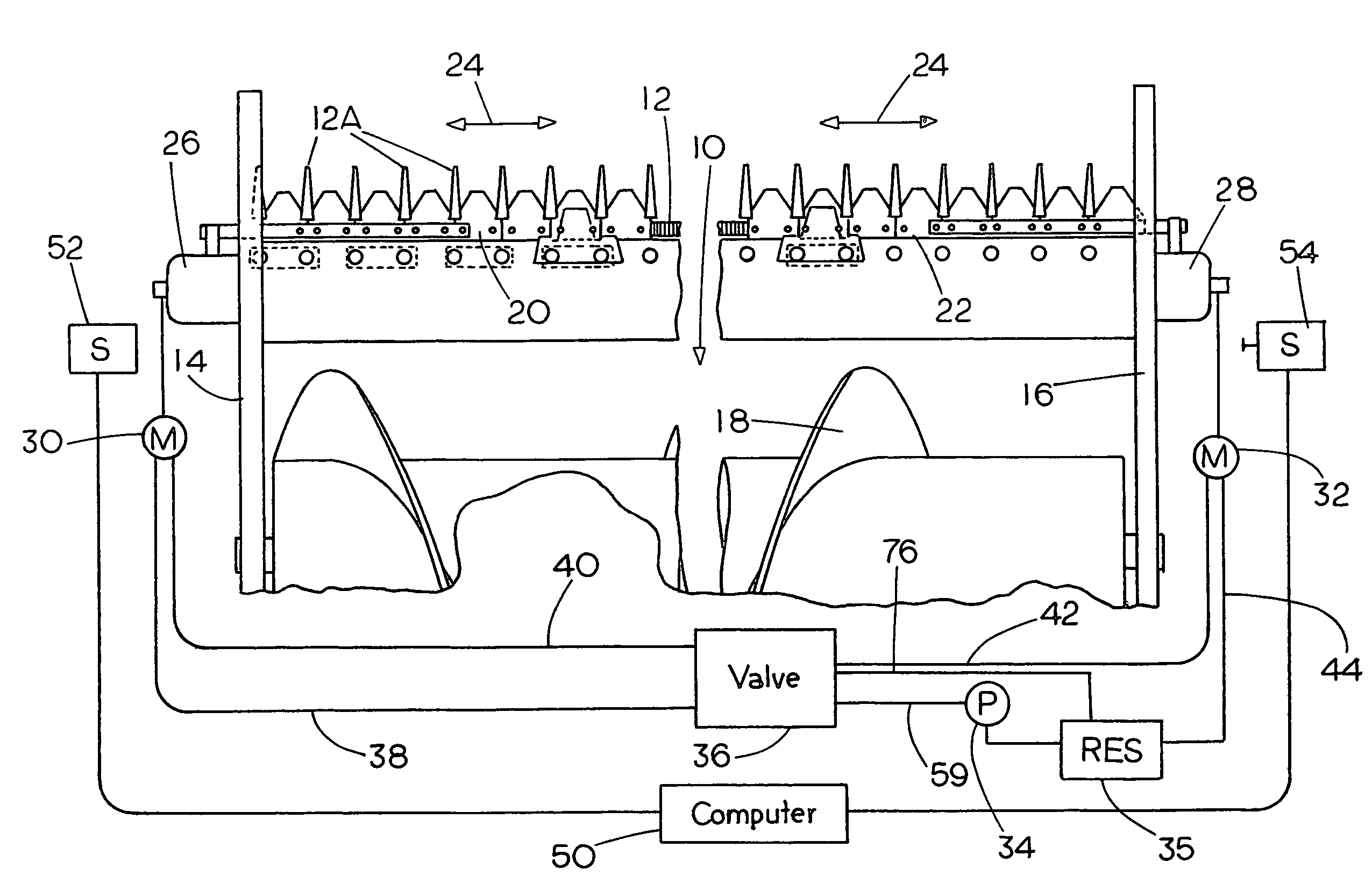
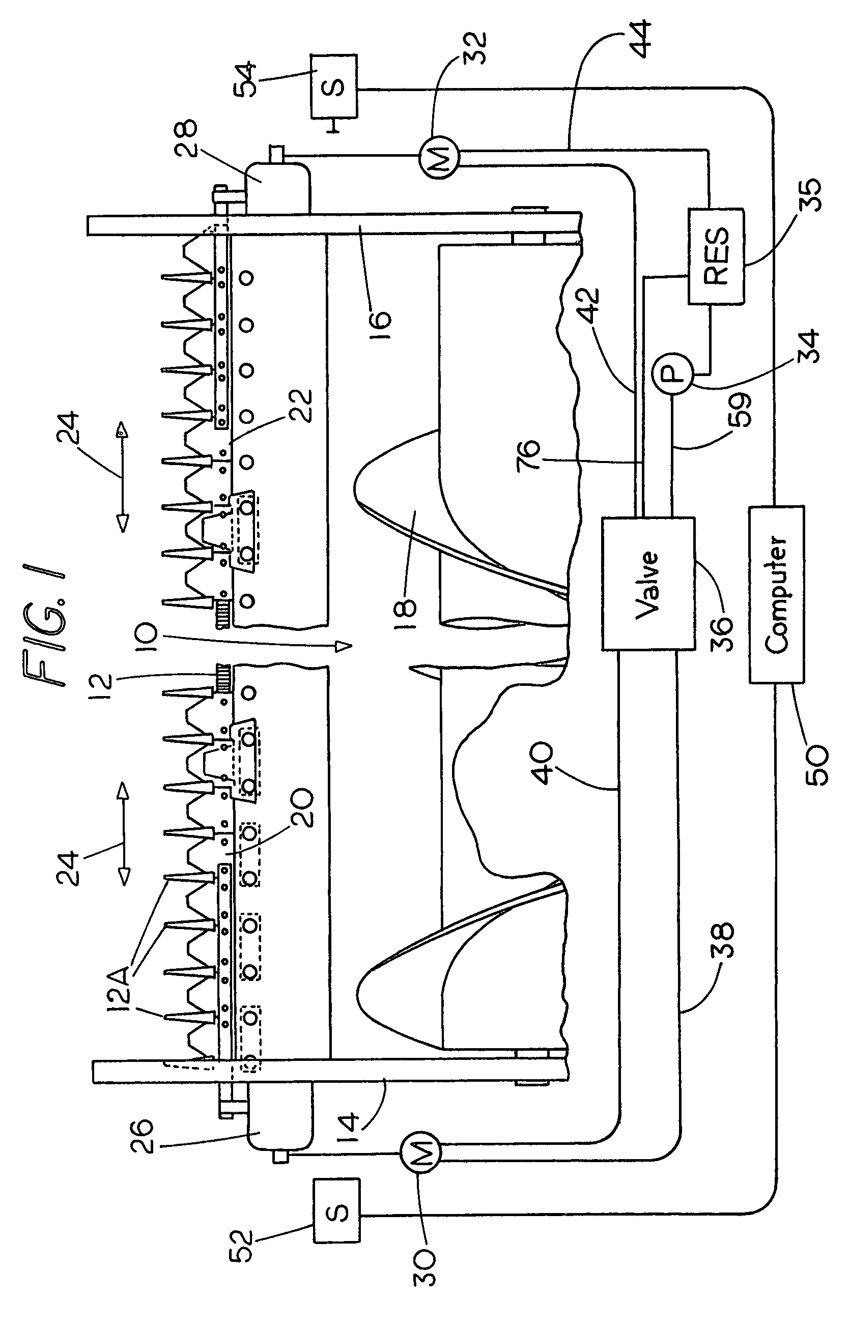
[0019]Referring first to FIG. 1, a fragmentary portion of a harvester or combine header 10 is schematically shown. The header is shown as a combine header and has a cutter bar assembly 12 at a leading edge thereof, and divider side panels 14 and 16 along the ends of the header. The cutter bar has a main transverse support bar for supporting the sickle sections 20 and 22, and carries sickle guards 12A. The header 10 includes a feed auger 18 that would receive material cut by the pair of sickle bar sections 20 and 22 that are supported on the cutter bar assembly 12, as the harvester header is moved forwardly. The FIG. 1 showing is a schematic showing, but the header length is such that the sickle bar sections 20 and 22 are individual, and will reciprocate back and forth as indicated by the double arrows 24. At the center portions of the header the sickle bar sections will have overlap so that when in synchronization there is a clean cut where the inner ends of the sickle bar sections ...


PUM


Abstract

A drive arrangement for split sickle bar sections of a harvester having a long cutter bar such as a combine, swather, mower-conditioner or the like utilizes separate drives for each sickle bar section, and provides for synchronizing the movement of the sickle bar sections so that they reach the respective ends of the reciprocating path simultaneously. In one form series connected first and second hydraulic motors are used, and the first motor in the series connection is reduced in speed from that which would be obtained from the full flow of a pump, by passing a portion of the pump fluid flow to a flow line leading to the second motor, a bleed valve bleeds off a portion of the flow in the flow line to regulate the second motor speed and position to match the speed and position of the first motor in response to signals indicating the position of the sickle bar sections. The sickle bar sections are thus synchronized.

Description

BACKGROUND OF THE INVENTION[0001]This disclosure relates to a drive for split sickle bars on harvester headers, such as combines, swathers, mower-conditioners and similar crop and hay cutters, where the cutter bar and sickle are long, so two sickle bar sections are reciprocated in opposite directions, and operated with separate reciprocating drives. The sickle bar sections move in opposite directions as they are separately stroked, and the present disclosure teaches synchronizing the drives so that the sickle bar sections will not go out “of time” and cause objectionable vibration.[0002]Large harvesters and combines for harvesting grain have headers that are up to at least 36 feet long, and it is common practice to have a split sickle bar, that is, two sickle bar sections driven from the opposite ends of the header and the moving linearly in opposite directions. It is also well known to use a “wobble” drive that converts a rotary motion into a linear motion for driving the sickle ba...

Claims


Application Information

Patent Timeline
Patent Type & Authority Patents(United States)
IPC IPC(8): A01D34/13
CPCA01D34/38
Inventor MAJKRZAK, DAVID
Owner BJ SERVICES CO
Why Eureka
Try Eureka