Overlay error detection

a technology of overlay error and detection capability, applied in the field of overlay error detection, can solve the problems of small depth of focus, vibration in the system for detecting overlay errors, and the position of beams to shift, so as to improve the signal-to-noise ratio, improve the edge detection capability and hence the sensitivity of overlay error measurement, and improve the effect of image quality and contras

Inactive Publication Date: 2006-05-11
KLA CORP
View PDF26 Cites 25 Cited by
  • Summary
  • Abstract
  • Description
  • Claims
  • Application Information

AI Technical Summary

Benefits of technology

[0010] Conventional methods for measuring overlay errors employ high numerical aperture objectives for collecting light from two target structures, where high numerical aperture objectives are used to maximize the resolution and hence the edge definition. The target structures may include an inner box at a higher elevation compared to the outer box. Since the collection objective employed in conventional methods has a high numerical aperture, this necessarily means that it has a small depth of focus. Thus, if the objective is positioned so that radiation from the inner box is focused onto the detector, then light collected from the outer box at a lower elevation will be out of focus with respect to the detector. Hence, in order to accurately measure both the inner and outer boxes, it is necessary to measure the target twice, known in the field as “double grab” with different optical focuses, so that radiation from both the inner and outer boxes may be focused onto the detector. Since two measurements are required instead of one as in a “single grab” measurement, this adversely affects throughput and is disadvantageous. Furthermore, where the detection system is subject to vibrations, such as in a wafer processing environment, vibrations may cause the optical alignment to shift between the two measurements, which may result in errors in the overlay error measurement. According to another aspect of the invention, the collection objective has a medium numerical aperture and therefore a larger depth of focus. Hence this increases the likelihood that radiation from both the inner and outer boxes or other structures at different elevations will be adequately focused onto corresponding detectors simultaneously so that there is no need to measure the target twice. Therefore, there are more applications where single grab is possible so that throughput is not adversely affected for such applications. Furthermore, since a medium numerical aperture increases the odds for adequate information to be obtained for overlay error measurement in one measurement, the system is robust and less affected by vibrations.
[0016] Other aspects of the invention relate to processing of radiation data collected from the two structures of the target. After a two-dimensional image of the target has been obtained, at least one one-dimensional signal may be derived from the image and used for determining an overlay error between the two structures. Where the one-dimensional signal is derived by averaging data in the image, the signal-to-noise ratio may be improved.
[0017] In conventional processing of data in overlay error detection, only data in portions of images at or close to edges of objects such as boxes or bars are used and the system is strongly dependent on the quality and contrast of the images. Modern chemical mechanical polishing processes tend to reduce the contrast of the target so that conventional methods may no longer be adequate. According to another aspect of the invention, the two-dimensional image of the target is represented by at least one signal which is an analytical function of position in the image. A curve fitting process of the at least one signal to data from the image of the two structures is then preferably used to determine an overlay error. When the image of the two structures is represented by at least one signal which is an analytical function, more information from the two-dimensional image is used for finding overlay errors compared to conventional methods and yields more accurate results. The curve fitting process further improves detection accuracy and precision.

Problems solved by technology

When so integrated, any system for detecting overlay errors is subject to vibrations.
If the detection system requires scanning light beams across targets, vibrations may cause the position of the beams to shift over time.
Since the collection objective employed in conventional methods has a high numerical aperture, this necessarily means that it has a small depth of focus.
Since two measurements are required instead of one as in a “single grab” measurement, this adversely affects throughput and is disadvantageous.
Furthermore, where the detection system is subject to vibrations, such as in a wafer processing environment, vibrations may cause the optical alignment to shift between the two measurements, which may result in errors in the overlay error measurement.
In an environment where the collection system is subject to vibrations, the measurement accuracy will be adversely affected by the vibrations if the data collection is over a time period where the optical alignment changes over such time period.

Method used


Image

  • Overlay error detection
  • Overlay error detection
  • Overlay error detection

Examples


Embodiment Construction

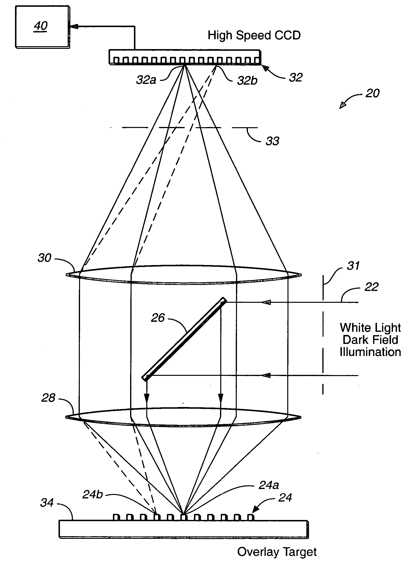
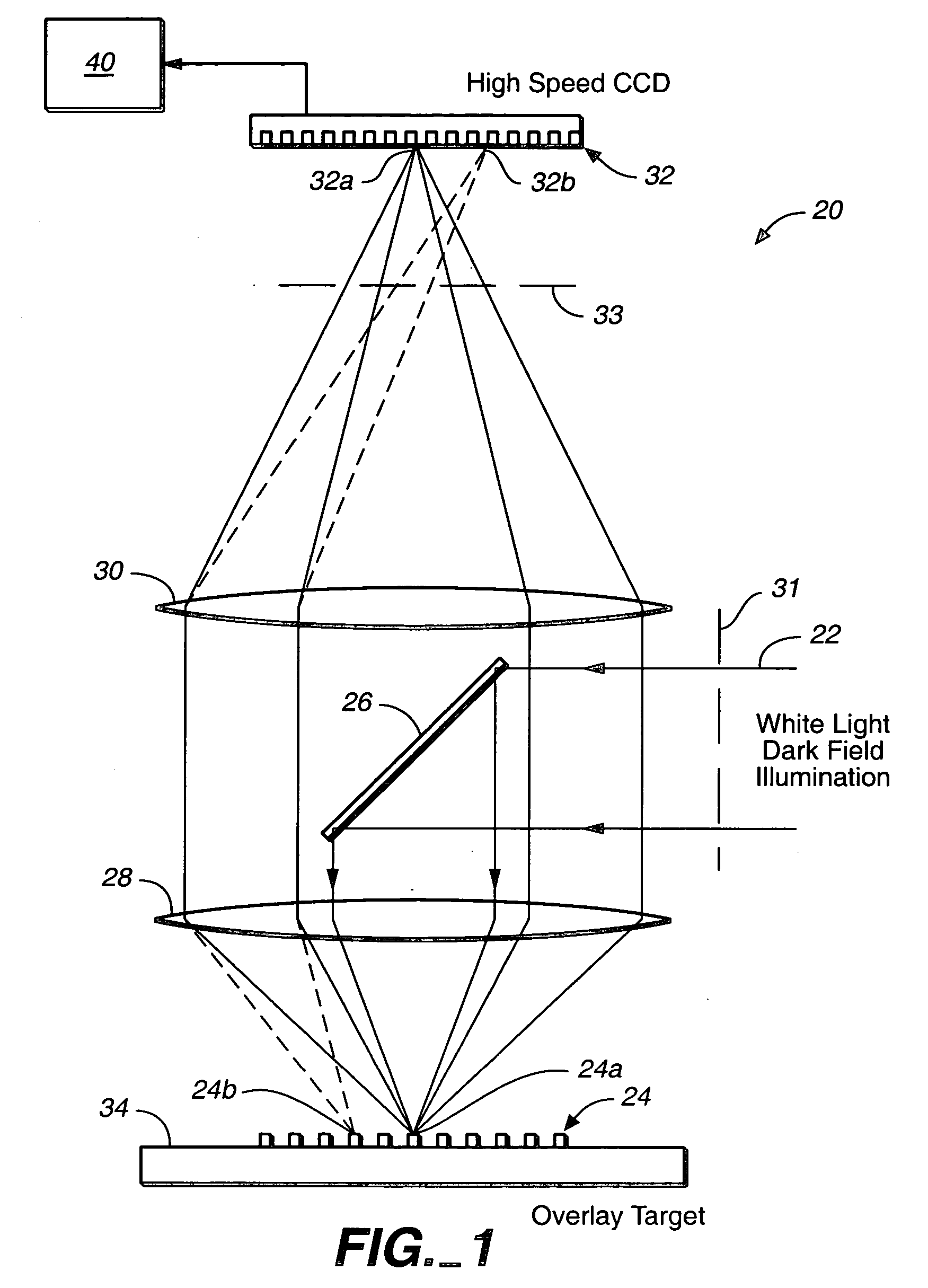
[0038]FIG. 1 is a cross-sectional view of a polychromatic (e.g. white light) or laser dark field imaging system to illustrate one embodiment of the invention. As shown in FIG. 1, the imaging system 20 includes a source (not shown) which supplies a laser beam 22 or a beam 22 of polychromatic radiation such as white light, where the beam 22 is reflected by a mirror 26 towards overlay target 24. Target 24 has two structures thereon: one on a current layer at a higher elevation than the other one on a previous layer. The two structures may be two gratings (they can also be the type that includes box(es) or bar(s), though not shown as such in FIG. 1), located on two different planes and are substantially parallel to the planes, where one of the two planes such as plane 34 (or any plane parallel thereto) may serve as a reference plane. Radiation from beam 22 that has been scattered by target 24 is collected by lens 28 and focused by lens 30 towards an array of detectors 32.

[0039] In FIG....


PUM


Abstract

An overlay target with gratings thereon is illuminated and radiation scattered by the target is imaged onto detectors. A phase difference is then detected between the outputs of the detectors to find the mis-alignment error. In another aspect, an overlay target with gratings or box-in-box structures is illuminated and radiation scattered by the target is imaged onto detectors located away from the specular reflection direction of the illumination in a dark field detection scheme. Medium numerical aperture optics may be employed for collecting the radiation from the overlay target in a bright or dark field configuration so that the system has a larger depth of focus and so that the two structures of the target at different elevations can be measured accurately at the same time. Analytical functions are constructed for the grating type targets. By finding the phase difference between the two gratings at different elevations, misalignment errors can be detected. Analytical functions are constructed as a model for box-in-box type targets where data points away from the edges of the box or bars can be used in the curve fitting. Symmetrical functions are employed to further reduce noise.

Description

CROSS-REFERENCE TO RELATED APPLICATION [0001] This application is a division of application Ser. No. 09 / 697,025, filed Oct. 26, 2000; which application is incorporated by reference as if fully set forth herein.BACKGROUND OF THE INVENTION [0002] This invention relates in general to overlay error detection and, in particular, to an imaging system for detecting misalignment of two structures and methods for determining overlay errors. [0003] Overlay error measurement requires specially designed targets to be strategically placed at various locations, normally in the street area between dies, on the wafers for each process. The alignment of the two overlay targets from two consecutive processes is measured for a number of locations on the wafer and the overlay error map across the wafer is analyzed to provide misalignment information. This information may then be used for the alignment control of wafer processing equipment. [0004] A key process control parameter in the manufacturing of ...

Claims


Application Information

Patent Timeline
Patent Type & Authority Applications(United States)
IPC IPC(8): G01B11/00G01B11/27H01L21/027
CPCG01B11/272G03F7/70633
Inventor NIKOONAHAD, MEHRDADZHAO, GUOHENGSHCHEGROV, ANDREI V.TSAI, BEN
Owner KLA CORP
Why Eureka
Try Eureka