Scroll machine with brushless permanent magnet motor

a permanent magnet motor and rolling machine technology, applied in the direction of positive displacement liquid engine, magnetic circuit rotating parts, magnetic circuit shape/form/construction, etc., can solve the problem of loose structure and achieve the effect of low cost and minimal variation in balancing mass

Active Publication Date: 2006-06-22
COPELAND LP
View PDF8 Cites 27 Cited by
  • Summary
  • Abstract
  • Description
  • Claims
  • Application Information

AI Technical Summary

Benefits of technology

[0008] On induction motors, the counterweights are typically attached to the rotor end rings by use of aluminum posts which are cast as part of the rotor. These cast posts extend through openings in the counterweights and the posts are swaged over to retain the counterweights on the rotor. Counterweights can also be pressed or bolted onto the rotating rotor or the drive shaft of the scroll machine. For reasons of low cost and minimal variation in the balancing mass, zinc die-cast counterweights have been the design of choice for comparable AC motor scroll compressors.

Problems solved by technology

The orbiting of one scroll member with respect to the other scroll member creates an imbalance which is typically counteracted using one or more counterweights.
This structure is somewhat loose due to the fact that it does not have cast aluminum rotor bars and end rings to hold it together.

Method used


Image

  • Scroll machine with brushless permanent magnet motor
  • Scroll machine with brushless permanent magnet motor
  • Scroll machine with brushless permanent magnet motor

Examples


Embodiment Construction

[0020] The following description of the preferred embodiment(s) is merely exemplary in nature and is in no way intended to limit the invention, its application, or uses.

[0021] The balancing system of the present invention is applicable to any type of rotary apparatus. For exemplary purposes only, the present invention is described in conjunction with a rotary compressor and, in particular, with a scroll-type refrigerant compressor.

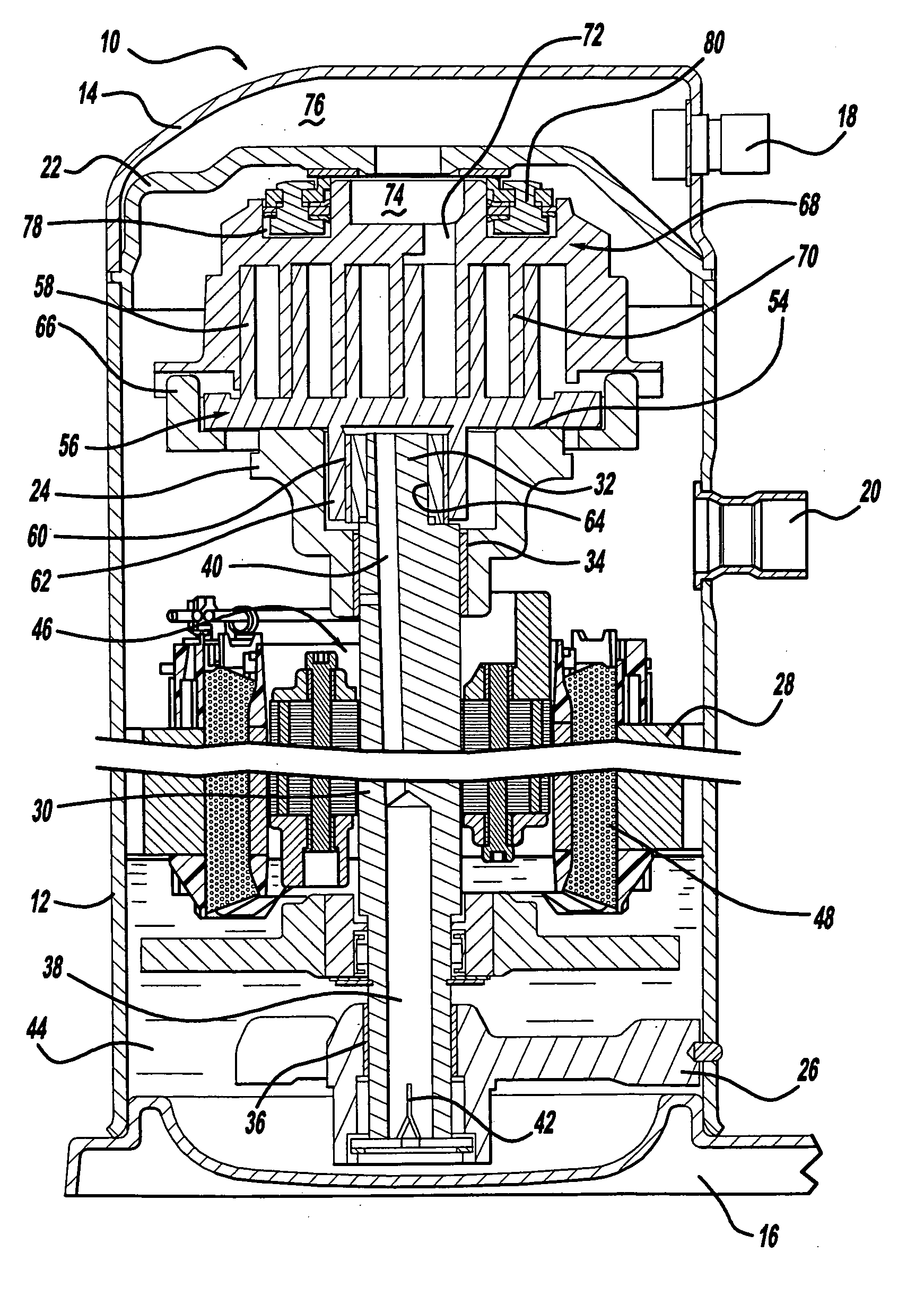
[0022] Referring now to the drawings in which like reference numerals designate like or corresponding parts throughout the several views, there is shown in FIG. 1 a scroll compressor which incorporates the balancing system in accordance with the present invention which is designated generally by reference numeral 10. Compressor 10 comprises a generally cylindrical hermetic shell 12 having welded at the upper end thereof a cap 14 and at the lower end thereof a base 16. Cap 14 is provided with a refrigerant discharge fitting 18, a suction fitting 20 and a ...


PUM


Abstract

A scroll machine is powered by a brushless permanent magnet motor. The rotor for the motor includes a rotor body formed by a plurality of laminations and an upper and lower counterweight made of zinc and located at opposite ends of the rotor body. An attachment member extends through the counterweights and the rotor body to secure the counterweights and the plurality of laminations. The counterweights include steel inserts which cooperate with the attachment member to provide a metal to metal clamping for the rotor body with a steel connection being maintained through the rotor.

Description

FIELD OF THE INVENTION [0001] The present invention relates to a scroll machine having a brushless permanent magnet motor. More particularly, the present invention relates to a system for incorporating upper and lower counterweights into a scroll machine which utilizes a brushless permanent magnet motor. BACKGROUND AND SUMMARY OF THE INVENTION [0002] For exemplary purposes, the system for incorporating upper and lower counterweights of the present invention will be described in association with a scroll machine. It is to be understood that it is within the scope of the present invention to utilize the system of the present invention with any device which includes a brushless permanent magnet motor and which requires counterweights. [0003] A class of machines exists in the art generally known as “scroll”machines for the displacement of various types of fluids. Such machines may be configured as an expander, a displacement engine, a pump, a compressor, etc., and many features of the p...

Claims


Application Information

Patent Timeline
Patent Type & Authority Applications(United States)
IPC IPC(8): F01C1/02F04C2/00F01C1/063F04C18/00
CPCF04C18/0215F04C23/008F04C29/0021F04C29/0085F04C2240/807H02K1/28H02K7/04H02K7/14Y10S417/902
Inventor DOEPKER, ROYELSON, JOHNRAMEY, WILLIAM
Owner COPELAND LP
Why Eureka
Try Eureka