String vibration suppressor for compound archery bows

a compound archery bow and vibration suppressor technology, applied in the field of compound archery bows, can solve the problems of shortening the useful life, affecting the performance of the bow, and affecting the accuracy of the bow, so as to reduce the displacement of the bow limb, and reduce the force applied to the limb anchor interfa

Inactive Publication Date: 2011-11-15
LARSON ARCHERY
View PDF36 Cites 27 Cited by
  • Summary
  • Abstract
  • Description
  • Claims
  • Application Information

AI Technical Summary

Benefits of technology

[0014]A bowstring-cable coupled bow reduces displacement of a bow limb, caused by twisting torque applied to the bow limb tip by the bowstring, compared to a vibration suppressor that anchors to only one side of a bow limb. Such limb displacement is reduced because the force applied by the bowstring is distributed to both the limb tip and to a cable. Therefore, the force applied to the limb anchor interface (even on a single-side of a limb) is reduced, compared to a non-coupled configuration. Consequently, the displacement caused by applying a twisting torque to a bow limb tip by a bowstring vibration dampening device including bowstring-cable coupling is reduced compared to a string vibration suppressor that anchors to only one side of a bow limb.

Problems solved by technology

Such vibrations are regarded as undesirable for several reasons.
Moreover, the vibrations create noise, much as the vibrating string of a musical instrument.
String vibration also contributes to a foreshortened useful life for the bowstring, due to fatigue.
String vibrations, and their attendant disadvantages are particularly evident in compound bows.

Method used


Image

  • String vibration suppressor for compound archery bows
  • String vibration suppressor for compound archery bows
  • String vibration suppressor for compound archery bows

Examples


Embodiment Construction

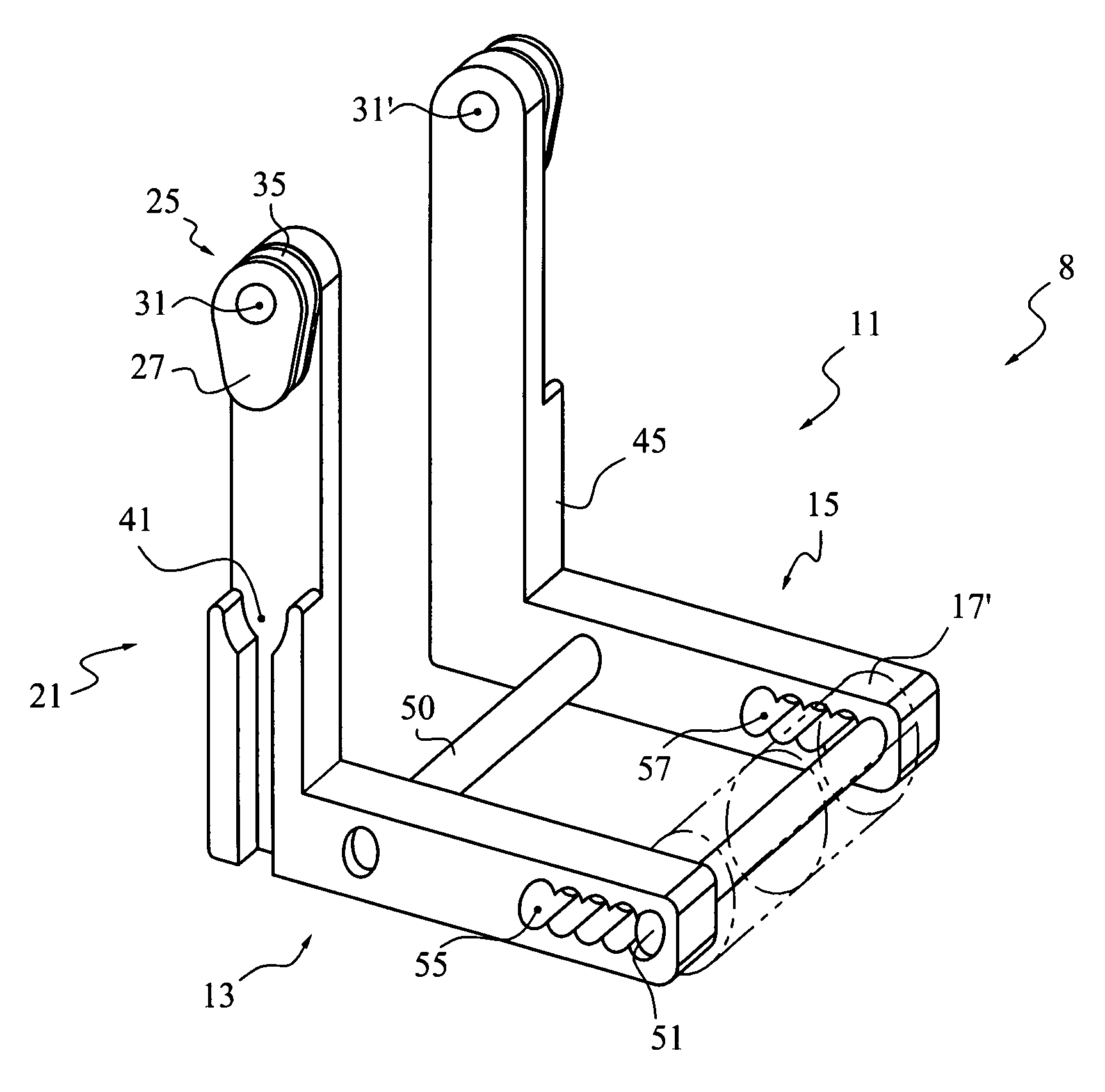
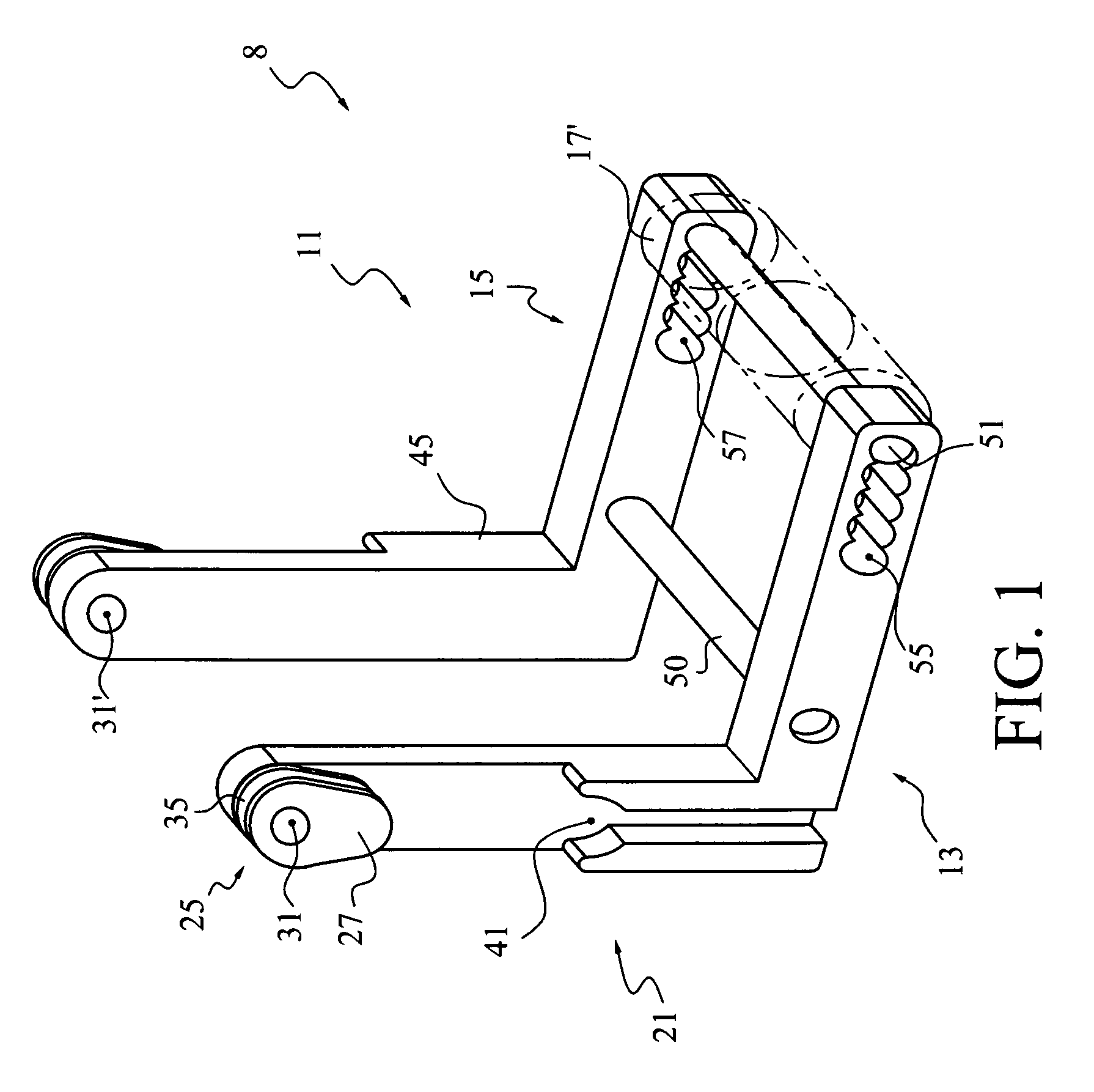
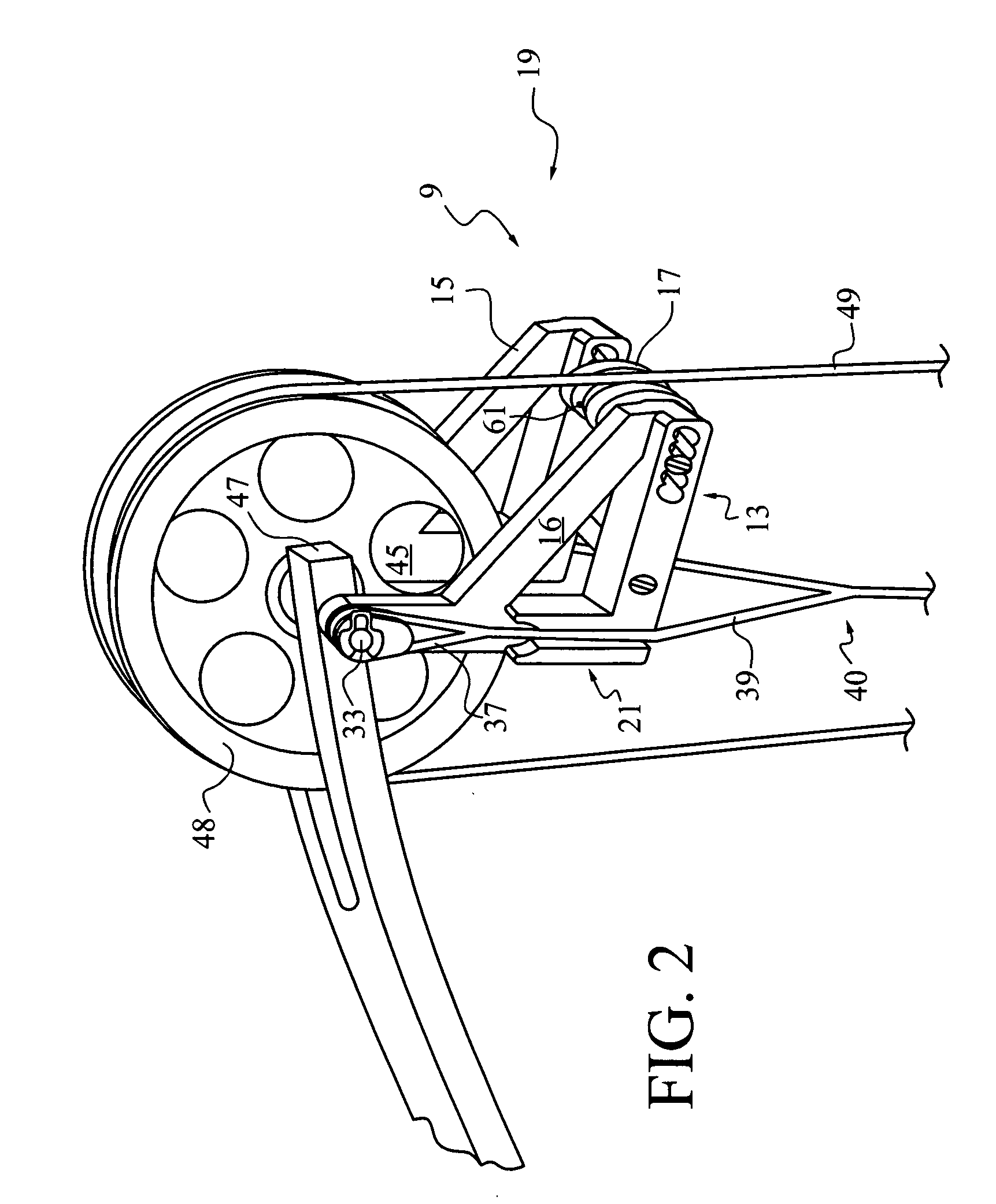
[0023]First and second embodiments of string vibration suppressors are illustrated in FIGS. 1 and 2, generally at 8 and 9, respectively. The embodiments illustrated in FIGS. 1 and 2 are similar, differing only in minor details. They each comprise an accessory capable of incorporation into the yoke harness portion of the riggings for compound bows of widely varying construction. Similar devices can be customized to specific bow constructions and supplied as original equipment.

[0024]An operable frame structure, generally 11, comprises approximately parallel side supports, generally 13, 15, respectively. Each support may be roughly “L-shaped,” as shown by FIG. 1. In one alternative construction, cross supports 16 may be added, as shown by FIG. 2, rendering the side supports generally triangular. It is apparent that many other configurations would be equally capable of holding a dampening member (bumper) 17, approximately as shown by FIG. 2, spaced apart between pulley assemblies of the...


PUM


Abstract

A vibration dampening device for use on compound archery bows. A device may be associated with one or more bow limb, with each device disposing a vibration damping bumper in position to shorten the vibrating length of the bow string at brace, compared to the vibrating length of a bow string of a comparable bow lacking the device(s). Certain embodiments couple bowstring vibration at brace with one or more cable. Preferred embodiments include a limb anchor adapted to distribute string-induced loading onto a bow limb at both sides of a string cam.

Description

BACKGROUND OF THE INVENTION[0001]1. Field[0002]This invention pertains to compound archery bows, and specifically to mechanisms for dampening string vibrations following the launch of an arrow.[0003]2. State of the Art[0004]Casting an arrow with an archery bow involves first nocking the arrow to a bowstring and then pulling the bowstring at the nock point from its rest (brace) position to a drawn position. The limbs of the bow are thereby flexed to store energy. The string is released to cast the arrow, and returns to its rest (or brace) position. The energy stored in the limbs is transferred primarily to the arrow, but in part to the string. This string energy is dissipated through vibrations. Such vibrations are regarded as undesirable for several reasons. A peculiar sensation is experienced by the archer as vibrations transfer through the grip of the bow to the archer's hand and forearm. Moreover, the vibrations create noise, much as the vibrating string of a musical instrument. ...

Claims


Application Information

Patent Timeline
Patent Type & Authority Patents(United States)
IPC IPC(8): F41B5/20
CPCF41B5/1426
Inventor LARSON, MARLOW W.
Owner LARSON ARCHERY
Why Eureka
Try Eureka