
Shot sleeve insert and method of retarding heat erosion within a shot sleeve bore

Inactive Publication Date: 2007-04-05
MANOFF PETER
View PDF29 Cites 9 Cited by
  • Summary
  • Abstract
  • Description
  • Claims
  • Application Information

AI Technical Summary

Benefits of technology

[0016] The insert comprises a cast iron insert having a first end, a second end and a body disposed between the first end and the second end, the body having a pour aperture in communication with a pour hole of a shot sleeve. The insert is removeably positioned within a groove of the shot sleeve wherein the molten material that is dispensed from the pour hole and int

Problems solved by technology

This heat erosion is a major cause of shot sleeve failure.
These methods do not provide sufficient erosion protection.
Additionally, these methods require costly equipment to minimize erosion.
Furthermore, these methods require substantial production and maintenance costs for the shot sleeve.

Method used


Image

  • Shot sleeve insert and method of retarding heat erosion within a shot sleeve bore
  • Shot sleeve insert and method of retarding heat erosion within a shot sleeve bore
  • Shot sleeve insert and method of retarding heat erosion within a shot sleeve bore

Examples


Embodiment Construction

[0017] The following detailed description illustrates the disclosure by way of example and not by way of limitation. The description clearly enables one skilled in the art to make and use the disclosure, describes several embodiments, adaptations, variations, alternatives, and uses of the disclosure, including what is presently believed to be the best mode of carrying out the disclosure.

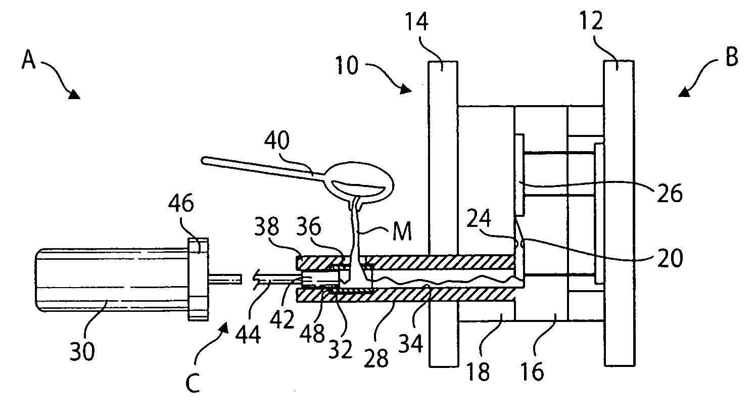
[0018] Referring to the drawings, a die casting assembly A generally shown includes a die assembly B defining the shape of an article to be cast and a material delivery assembly generally shown as C for forcing molten material M into the die assembly B to create cast objects (FIG. 1). While the present disclosure is described in connection with a horizontal casting system, the present disclosure is equally well suited for use with vertical casting systems. The terms outer and inner are used herein as expedients to describe the directions away from and toward the die assembly B respectively. Similarl...


PUM


Abstract

An insert for a die casting assembly. The insert comprises a cast iron insert having a first end, a second end and a body disposed between the first end and the second end, the body having a pour aperture in communication with a pour hole of a shot sleeve. The insert is removeably positioned within a groove of the shot sleeve wherein the molten material that is dispensed from the pour hole and into the pour aperture initially contacts the cast iron insert when the molten material flows into the cast iron insert such that the cast iron insert withstands heat erosion effects applied by the molten material to provide a smooth path for the plunger as the plunger reciprocates within a sleeve bore of the shot sleeve and pushes the molten material into a mold cavity.

Description

CROSS-REFERENCE TO RELATED APPLICATIONS [0001] This application claims priority under 35 U.S.C. §119(e) of U.S. Provisional Patent Application No. 60 / 716,678 filed Sep. 13, 2005, in the name of the present inventor and claims priority under 35 U.S.C. §119(e) of U.S. Provisional Patent Application No. 60 / 790,203 filed Apr. 7, 2006, in the name of the present inventor.STATEMENT REGARDING FEDERALLY SPONSORED RESEARCH [0002] Not Applicable. BACKGROUND OF THE DISCLOSURE [0003] This disclosure relates to an insert for a die casting apparatus, and in particular, to an insert that retards erosion of a shot sleeve bore used in the die casting apparatus. [0004] Die-casting is a common used technology for manufacturing material articles. [0005] Typically, the die casting apparatus includes a pair of die halves each formed with a void corresponding to a portion of the article to be cast. When the two die halves are brought together in proper alignment, their respective voids cooperate to form a...

Claims


Application Information

Patent Timeline
IPC IPC(8): B22D17/10
CPCB22D17/10B22D17/2023
Inventor MANOFF, PETER
Owner MANOFF PETER
Learn More