
Stress balanced cutting structure

a cutting structure and stress-balanced technology, applied in the direction of cad techniques, instruments, design optimisation/simulation, etc., can solve the problems of high cost of drilling a borehole for the recovery of hydrocarbons or minerals, ineffective hard rock formations of milled tooth roller cone bits, and inability to achieve the effect of hard rock formation recovery,

Inactive Publication Date: 2007-04-05
SMITH INT INC
View PDF4 Cites 17 Cited by
  • Summary
  • Abstract
  • Description
  • Claims
  • Application Information

AI Technical Summary

Problems solved by technology

By contrast, milled tooth roller cone bits are relatively ineffective in hard rock formations as may be encountered at greater depths.
Drilling a borehole for the recovery of hydrocarbons or minerals is typically very expensive due to the high cost of the equipment and personnel that are required to safely and effectively drill to the desired depth and location.
As is thus obvious, this process, known as a “trip” of the drill string, requires considerable time, effort, and expense.
Such whirling subjects the cutting elements on the bit to increased loading, which causes the premature wearing or destruction of the cutting elements and a loss of penetration rate.
Although the spiral arrangement was once widely employed, this arrangement of cutting elements was found to wear in a manner to cause the bit to assume a cutting profile that presented a relatively flat and single continuous cutting edge from one element to the next.
Not only did this decrease the ROP that the bit could provide, but it also increased the likelihood of bit vibration or instability which can lead to premature wearing or destruction of the cutting elements and a loss of penetration rate.
All of these conditions are undesirable.
A low ROP increases drilling time and cost, and may necessitate a costly trip of the drill string in order to replace the dull bit with a new bit.
Excessive bit vibration may dull or damage the bit to an extent that a premature trip of the drill string becomes necessary.
However, having both cutting elements on the same profile causes the leading cutting element to experience much higher work rate and forces than the trailing cutting element.
This results in a fast, yet fragile cutting structure.
A single set with essentially equalized forces may result in a more durable cutting structure, but the structure is mechanically less stable.
In bits where smaller and larger cutting elements are mounted on the bit, the smaller cutting elements experience higher stresses and usually fail before the larger cutting elements.
That is, the life of the smaller cutting elements may limit the durability and life of the bit.
Failure of cutting elements may be a result of, for example, impact loading on the cutting elements, wear induced on the elements, the work rate of the cutting elements, stress on the cutting elements, etc.
While these methods of protection have met with some success, drill bits still experience cutting element failure.

Method used


Image

  • Stress balanced cutting structure
  • Stress balanced cutting structure
  • Stress balanced cutting structure

Examples


Embodiment Construction

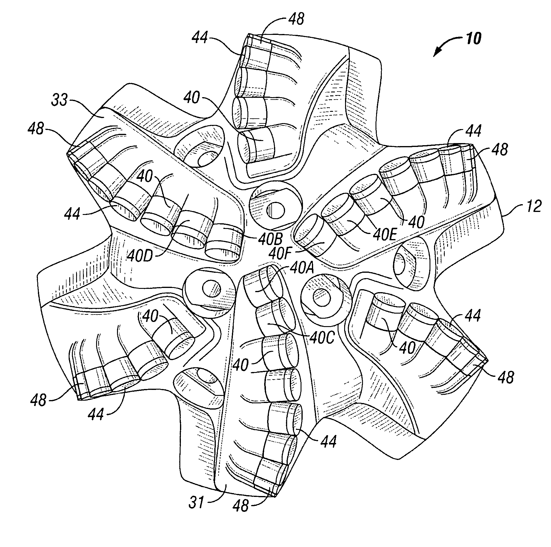
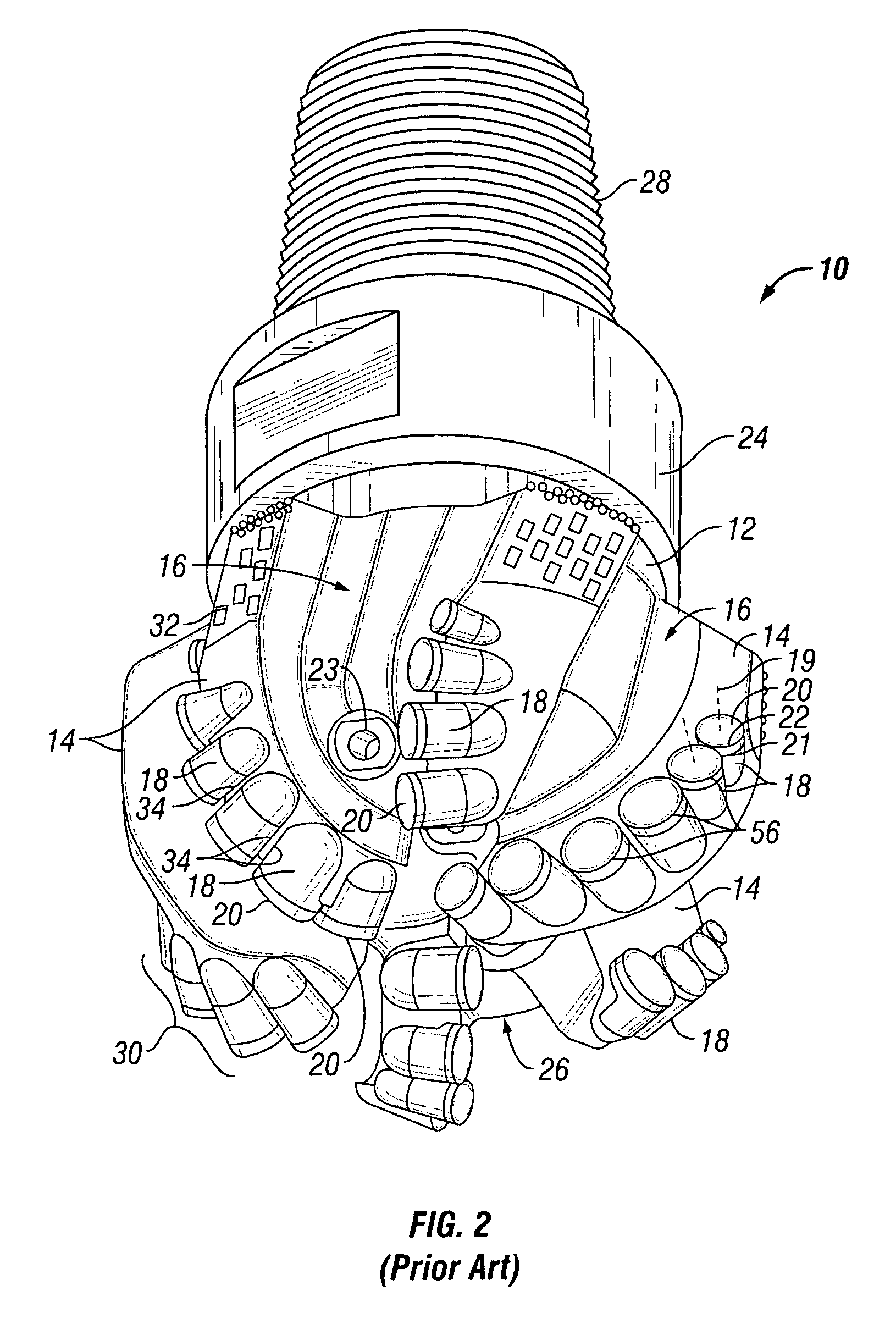
[0036] During drilling, the life of a drill bit is often limited by the failure rate of the cutting elements mounted on the bit. Cutting elements may fail at different rates depending on a variety of factors. Such factors include, for example, the geometry of the cutting element, position of the cutting elements on the bit, the orientation of the cutting element with respect to the formation being drilled, cutting element material properties, etc. In one aspect, embodiments of the present invention relate to a method of designing a fixed cutter drill bit to maintain mechanical stability of the bit and control the failure rate of the cutting elements. In another aspect, embodiments of the present invention relate to a fixed cutter drill bit with cutting elements mounted thereon so as to reduce the difference or variation of characteristic values associated with a failure mode between at least two cutting elements until the variation is within a predetermined range.

[0037] Embodiments...


PUM


Abstract

A method for designing a drill bit including selecting a characteristic associated with a failure mode. A first value of the characteristic of a first cutting element and a second value for the characteristic of a second cutting element are determined. The method also includes determining whether a difference between the first value and the second value is within a predetermined range. A cutting element design parameter for the first cutting element is adjusted if the difference is outside the predetermined range. The determining first and second values, determining the difference, and adjusting a cutting element design parameter are repeated until the difference is within the predetermined range.

Description

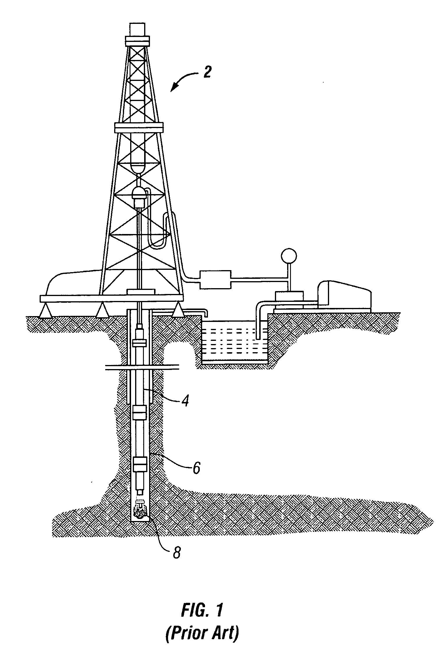
BACKGROUND OF INVENTION [0001] 1. Field of the Invention [0002] The invention relates generally to fixed cutter drill bits. [0003] 2. Background Art [0004] In drilling a borehole in the earth, such as for the recovery of hydrocarbons, minerals, or for other applications, it is conventional practice to connect a drill bit on the lower end of an assembly of drill pipe sections which are connected end-to-end so as to form a “drill string.” The drill string is rotated by an apparatus that is positioned on a drilling platform located at the surface of the borehole. Such an apparatus turns the bit and advances it downwardly, causing the bit to cut through the formation material by either abrasion, fracturing, shearing action, or through a combination of all such cutting methods. While the bit is rotated, drilling fluid is pumped through the drill string and directed out of the drill bit through nozzles that are positioned in the bit face. The drilling fluid is provided to cool the bit and...

Claims


Application Information

Patent Timeline
IPC IPC(8): G06F17/50
CPCE21B10/43E21B10/55G06F17/50G06F2217/16G06F2111/10G06F30/00G06F30/17E21B10/54G06F30/20
Inventor SHEN, YUELINZHANG, YOUHEWILLIAMS, JOHNCARIVEAU, PETERJANSSEN, MICHAEL
Owner SMITH INT INC
Learn More