Nuclear medicine diagnostic apparatus, positron emission computed tomography apparatus, and detector units

a diagnostic apparatus and nuclear medicine technology, applied in tomography, x/gamma/cosmic radiation measurement, instruments, etc., can solve the problems of increasing current leakage, reducing increasing dust, so as to increase current leakage, and reduce energy resolution and time resolution

Inactive Publication Date: 2007-04-12
HITACHI LTD
View PDF4 Cites 30 Cited by
  • Summary
  • Abstract
  • Description
  • Claims
  • Application Information

AI Technical Summary

Benefits of technology

The patent text is discussing the importance of temperature, moisture-proofing, and dust-proofing in radiation detectors, especially semiconductor detectors. These detectors need to be applied with a high-voltage bias, but if dust sticks to them, it can increase current leakage and reduce energy resolution and time resolution. Additionally, humidity can further decrease energy resolution and time resolution. The technical effect of this patent is to provide a solution to prevent dust and humidity from affecting the performance of radiation detectors.

Problems solved by technology

The technical problem addressed in this patent is the decrease in energy resolution and the resulting decrease in quantitative assessment accuracy during 3D imaging with PET due to the use of scintillators as radiation detectors. The use of semiconductor radiation detectors as an alternative to scintillators can improve energy resolution and image quality, but requires efficient cooling to maintain optimal performance.

Method used


Image

  • Nuclear medicine diagnostic apparatus, positron emission computed tomography apparatus, and detector units
  • Nuclear medicine diagnostic apparatus, positron emission computed tomography apparatus, and detector units
  • Nuclear medicine diagnostic apparatus, positron emission computed tomography apparatus, and detector units

Examples


Embodiment Construction

[0026] A nuclear medicine diagnostic apparatus according to a preferred embodiment of the present invention will be described hereunder with reference to FIGS. 1 to 5. Although the nuclear medicine diagnostic apparatus of the present embodiment will be described taking a PET apparatus as an example, the present invention is not limited to the PET apparatus and can be applied to other nuclear medicine diagnostic apparatuses such as a SPECT apparatus.

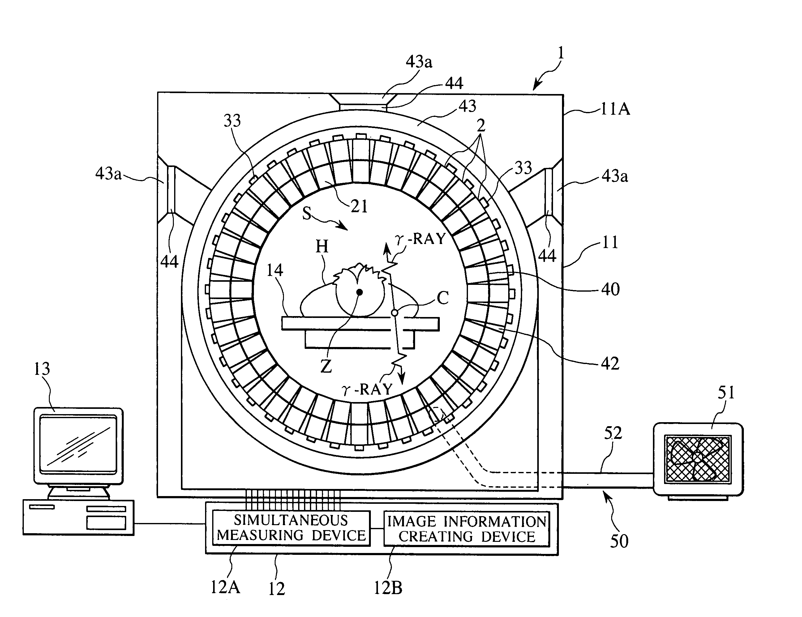
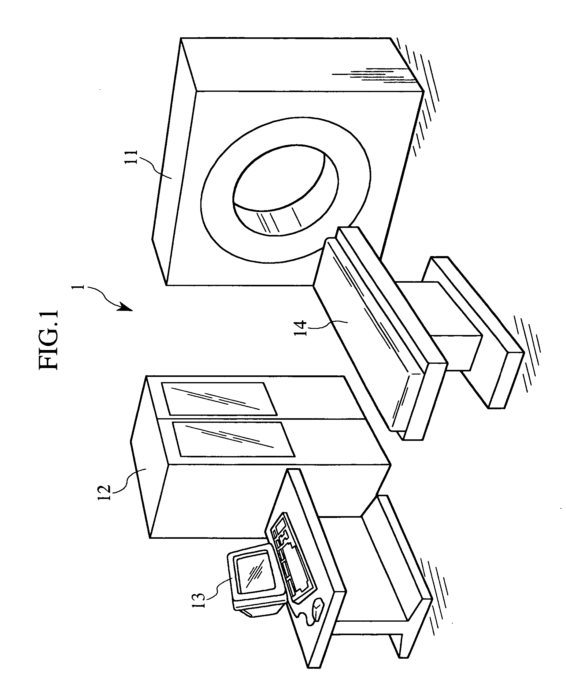
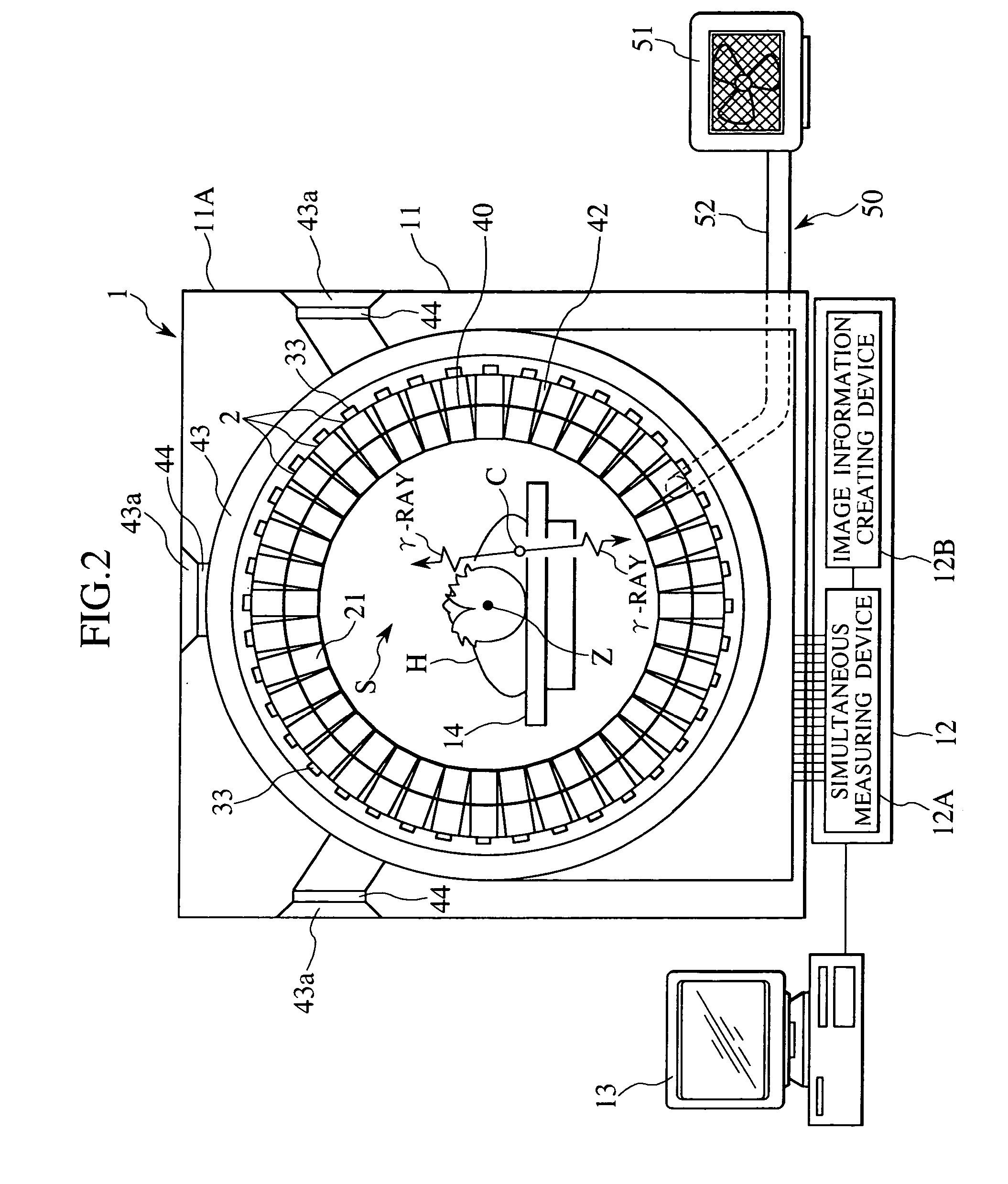
[0027] As shown in FIG. 1, PET apparatus 1 (nuclear medicine diagnostic apparatus) includes an image acquisition device 11, a data processor 12 which processes detection data obtained by the image acquisition device 11 during imaging and converts the detection data into image data, a display device 13 which makes a two-dimensional or three-dimensional display of the image data that the data processor 12 outputs, and a bed 14 on which to rest a human body (patient) as a human subject H of examination so as to be movable forward and backwa...


PUM


Abstract

A nuclear medicine diagnostic apparatus is provided that can improve time resolution and energy resolution and diagnosing accuracy by enhancing radiation detectors in terms of moisture-proofing and dust-proofing effects while efficiently cooling the radiation detectors. The apparatus has a first region A in which radiation detectors are to be accommodated, and a second region B in which signal processors are to be accommodated. These regions are provided inside a housing member 5 via an adiabatic member 7. The housing member 5 also has a ventilation port 8 formed to communicate with the first region A and equipped with an anti-dust filter. Ventilation holes 34 are formed to communicate with the first region B and serving as entrances for cooling air. Unit fans 33 serve as exits for the cooling air.

Description


Claims


Application Information

Patent Timeline
Owner HITACHI LTD
Why Eureka
Try Eureka