
Apparatus and method for automatically adjusting white point during video display

a technology of automatic adjustment and video display, which is applied in the direction of television system, color signal processing circuit, instruments, etc., can solve the problems of negative impact on the appearance of the image to the viewer, damage to the intended white point, etc., to achieve the effect of improving the display imag

Inactive Publication Date: 2007-04-12
TEXAS INSTR INC
View PDF19 Cites 46 Cited by
  • Summary
  • Abstract
  • Description
  • Claims
  • Application Information

AI Technical Summary

Benefits of technology

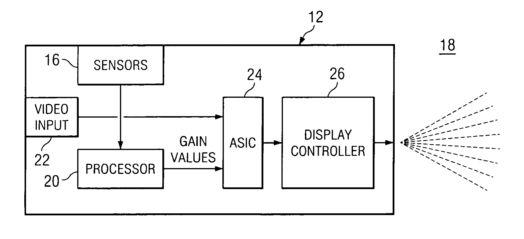
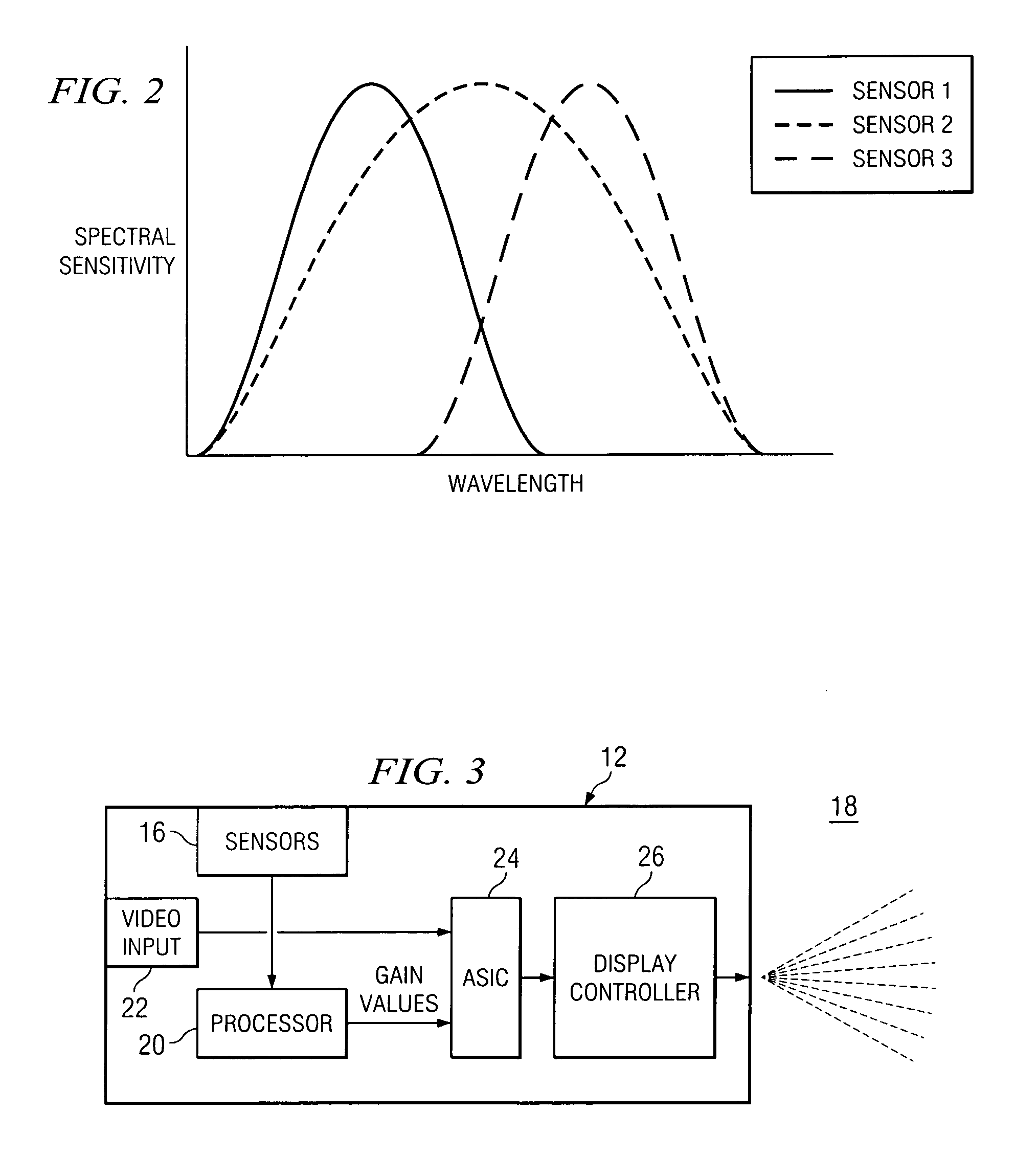
[0005] The present disclosure relates to improving display images by implementing systems and processes for automatically adjusting the white point and contrast of such images to account for changes in ambient light. In one embodiment, a display system includes a display device having sensors for recording the red (R), green (G) and blue (B) values for ambient light (i.e., light in the viewing area extrinsic to the display device) and measuring the intensity of such light. The sensors feed these values into a processor, which calculates R, G, B gain values to be applied to the video input R, G, B values. In this manner...

Problems solved by technology

Display system images can be negatively affected in a variety of manners.
For example, the colorfulness of an image can degrade under certain conditions, thereby negatively affecting the appearance of the image to the viewer.
The intended white point, however, can be corrupted by extrinsic or ambient light due to the effect such light has on the image perceived by the viewer.
Indeed, the sunroom will have an abundance of ambient light that will negatively affect the perceived image.
The degradation of the image in the sunroom can be attributed to the white point and contrast adjustment caused by ambient light.
However, such devices are typically difficult to operate and require manual intervention to effect the desired change.

Method used


Image

  • Apparatus and method for automatically adjusting white point during video display
  • Apparatus and method for automatically adjusting white point during video display
  • Apparatus and method for automatically adjusting white point during video display

Examples


Embodiment Construction

[0015] Digital video signals generally comprise a series of image frames, which include a large number of image pixels to formulate a desired image. Ideally, the images displayed by the image frames are of a desirable colorfulness from the perspective of the viewer. However, ambient light can negatively affect the desired image by corrupting the white point of the display device. The principles of the present disclosure seek to improve the resultant image by automatically adjusting the white point of the perceived image.

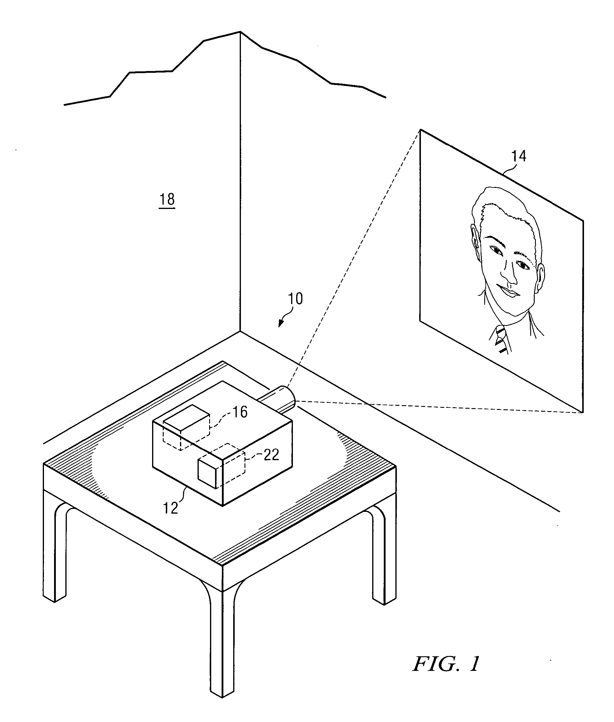
[0016] Referring to FIG. 1, in one embodiment, a display system 10 includes a video projector 12 for projecting video images on a projector screen 14. Although exemplary embodiments will be described in the context of video projector systems, it is to be appreciated that the principles of the present disclosure can be adapted to a variety of display systems, including digital rear projection televisions (e.g., a Digital Light Processing or DLP® televisions), front p...


PUM


Abstract

The present disclosure relates to systems and processes for automatically adjusting the white point of displayed images to account for changes in ambient light. In one embodiment, a display system includes a display device having sensors for recording the red (R), green (G) and blue (B) values for ambient light and measuring the intensity of such light. The sensors feed these values into a processor, which calculates R, G, B gain values to be applied to the video input R, G, B values. In this manner, the display device can account for changes in ambient light to adjust the perceived white point accordingly. Related methods for automatically adjusting the white point of a perceived image are also described.

Description

TECHNICAL FIELD [0001] The present disclosure relates to automatic adjustment of white point of display systems. BACKGROUND [0002] Display system images can be negatively affected in a variety of manners. For example, the colorfulness of an image can degrade under certain conditions, thereby negatively affecting the appearance of the image to the viewer. Often, ambient light distorts the colorfulness of an image by corrupting the “white point” of an image—i.e., the point that can be considered as the whitest point in the image—and overall image contrast. [0003] Display systems each have their own intended white point, which is typically determined by the manufacturing specifications of the device. The intended white point, however, can be corrupted by extrinsic or ambient light due to the effect such light has on the image perceived by the viewer. For example, an image in a dark room will look more clear and colorful than an image being viewed in a sunroom. Indeed, the sunroom will ...

Claims


Application Information

Patent Timeline
IPC IPC(8): H04N5/58
CPCH04N5/58H04N9/3182H04N9/3194H04N9/73H04N21/42202H04N21/4318G09G2320/0242G09G2360/144
Inventor RAMANATH, RAJEEVPETTITT, GREGORY S.
Owner TEXAS INSTR INC
Learn More