Liquid crystal display apparatus

a display apparatus and liquid crystal technology, applied in static indicating devices, instruments, non-linear optics, etc., can solve the problems of deteriorating the image picture quality, deteriorating the picture quality of an image displayed sometimes occurrence of light leakage in the display region, so as to prevent “light leakage” in the light receiving region and improve the image picture quality of the display image

Active Publication Date: 2009-03-12
JAPAN DISPLAY INC
View PDF26 Cites 4 Cited by
  • Summary
  • Abstract
  • Description
  • Claims
  • Application Information

AI Technical Summary

Benefits of technology

[0027]With the liquid crystal display apparatus, “light leakage” in the light receiving region can be prevented, and consequently, the image picture quality of the display image can be improved.

Problems solved by technology

However, in the liquid crystal panel described above, since the light receiving region is open so as to allow light to be transmitted therethrough, back light irradiated from the back side is sometimes transmitted in the light receiving region to the front face side and deteriorates the image picture quality.
Therefore, “light leakage” sometimes occurs in the display region.
Where such light leakage occurs, portions other than the pixels become bright, resulting in deterioration of the picture quality of an image displayed in the display region.
However, to form the light blocking layer on the TFT array substrate on which the light receiving elements are formed is sometimes difficult from a restriction to the layout.
Further, where the light blocking layer is provided on the opposing substrate opposing to the TFT array substrate, it is necessary to take the error when the opposing electrode is mounted on the TFT array substrate on which the light receiving elements are formed into consideration.
This gives rise to necessity to increase the area of the light blocking layer, which results in drop of the numerical aperture of the display region and sometimes deteriorates the image picture quality.

Method used


Image

  • Liquid crystal display apparatus
  • Liquid crystal display apparatus
  • Liquid crystal display apparatus

Examples


first embodiment

(General Configuration of the Liquid Crystal Display Apparatus)

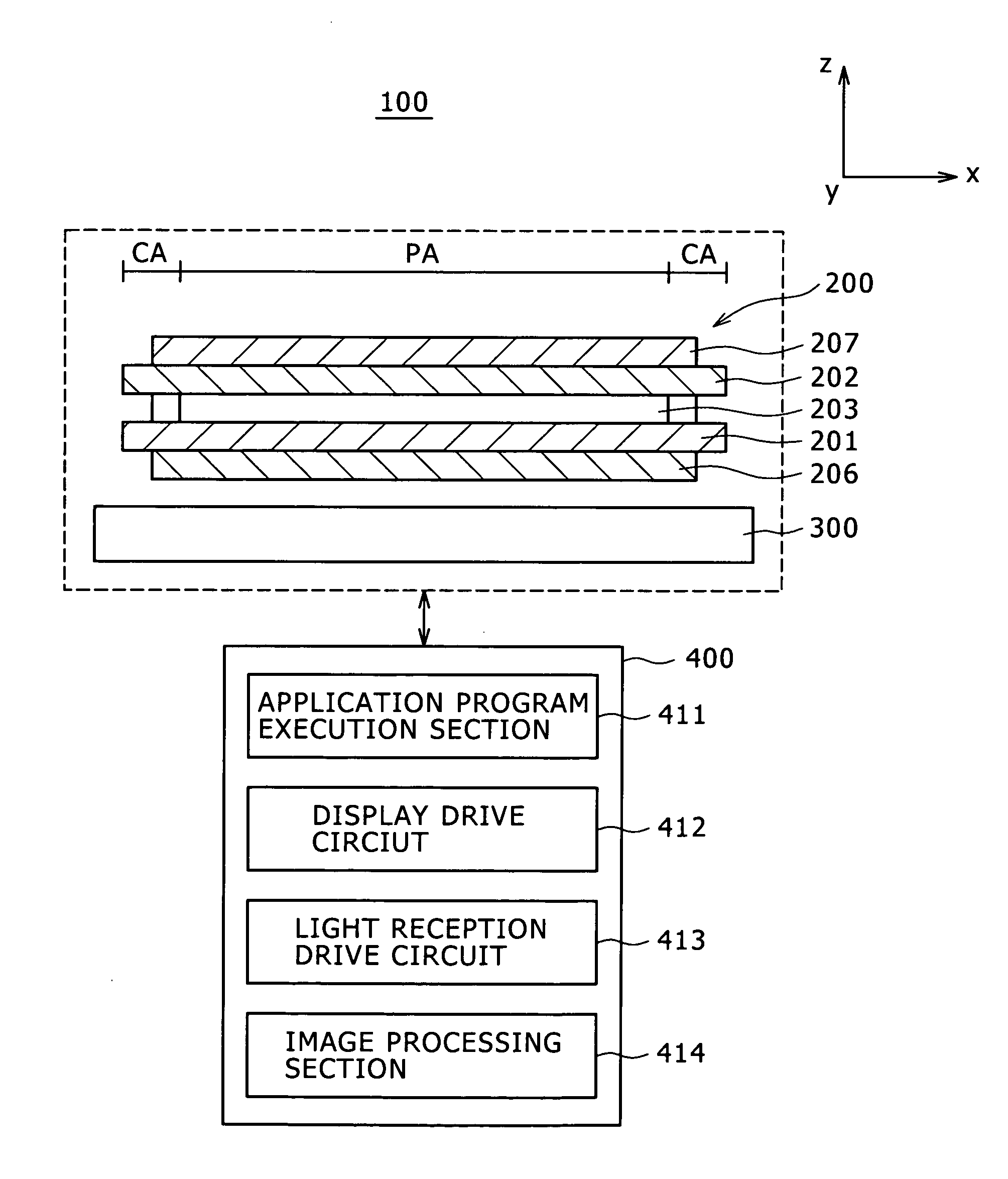
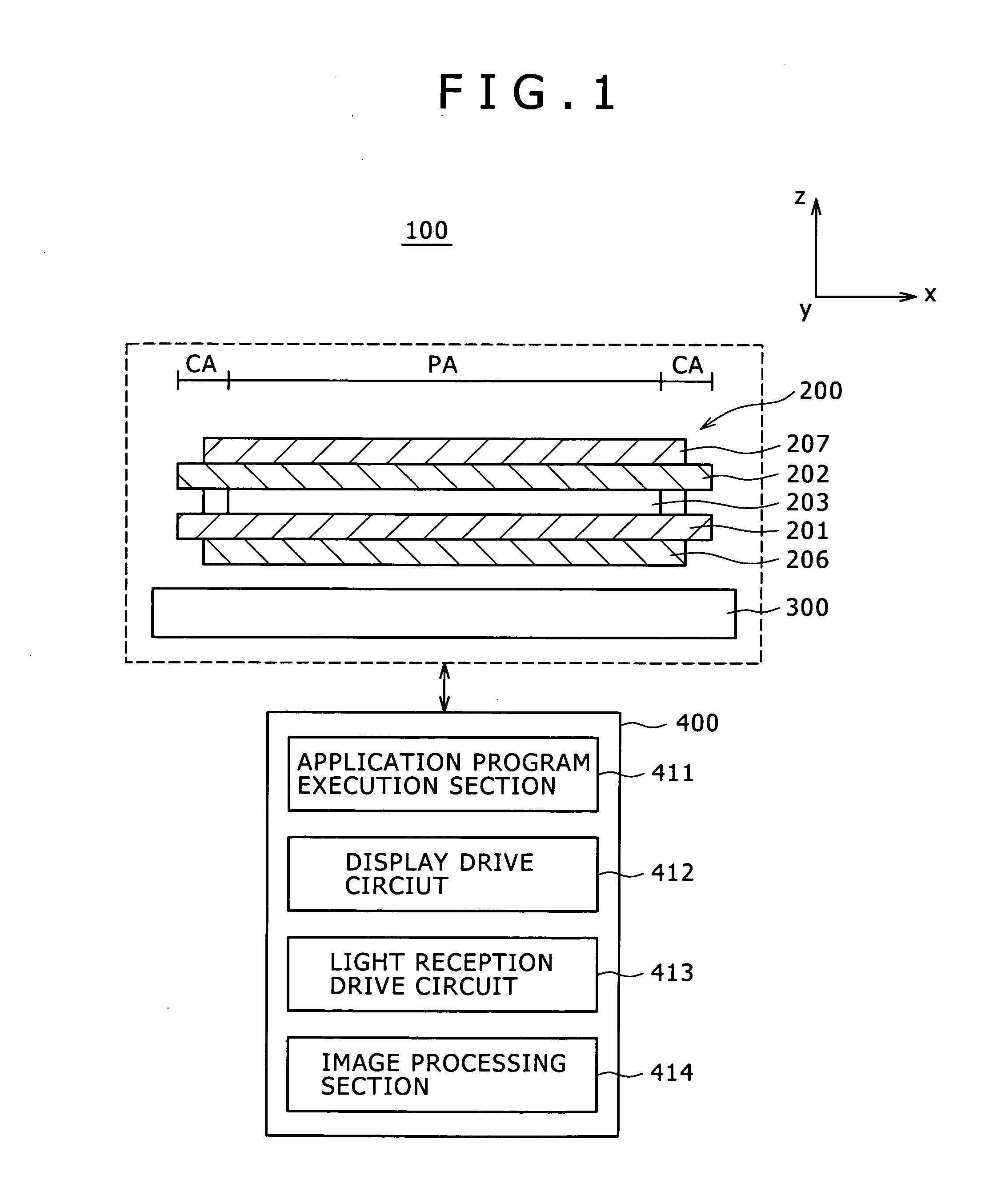
[0043]FIG. 1 shows a configuration of a liquid crystal display apparatus 100 according to a first embodiment of the present invention.

[0044]Referring to FIG. 1, the liquid crystal display apparatus 100 shown includes a liquid crystal panel 200, a backlight 300 and a control section 400. The components are successively described below.

[0045]The liquid crystal panel 200 includes a TFT array substrate 201, an opposing substrate 202 and a liquid crystal layer 203.

[0046]In the liquid crystal panel 200, the TFT array substrate 201 and the opposing substrate 202 are opposed in a spaced relationship from each other. The liquid crystal layer 203 is provided in a sandwiched relationship between the TFT array substrate 201 and the opposing substrate 202.

[0047]Further, a first polarizing plate 206 and a second polarizing plate 207 are disposed in an opposing relationship to each other on the opposite face sides of the liquid crystal...

second embodiment

[0127]FIG. 9 shows a liquid crystal panel 210 of a liquid crystal display apparatus according to a second embodiment of the present invention.

[0128]Referring to FIG. 9, as can be recognized from comparison with the liquid crystal panel 200 shown in FIG. 6, the liquid crystal panel 210 in the present embodiment is different in shape of the opposing electrode 23 formed on the opposing substrate 202 and is further different in that a conductive layer 64 formed separately on the opposing substrate 202. The liquid crystal display apparatus of the present embodiment is similar to that of the first embodiment except the differences just described, and overlapping description of the common configuration is omitted herein to avoid redundancy.

[0129]In the present embodiment, the opposing electrode 23 is provided such that, in the light transmission region TA of the display region PA, it corresponds to the plurality of pixel electrodes 62 formed so as to correspond to the pixels P.

[0130]On the...

third embodiment

[0135]FIG. 10 shows a liquid crystal panel 220 of a liquid crystal display apparatus according to a third embodiment of the present invention.

[0136]Referring to FIG. 10, as can be recognized from comparison with the liquid crystal panel 210 shown in FIG. 9, the opposing electrode 23 and the conductive layer 64 are formed on the opposing substrate 202 similarly as in the liquid crystal display apparatus of the second embodiment. However, the liquid crystal panel 220 in the present embodiment is different from that in the second embodiment in that the conductive layer 63 formed on the TFT array substrate 201 is not set to a grounded (GND) state. Further, the liquid crystal panel 220 in the present embodiment is different from that in the second embodiment in that the conductive layer 64 formed on the opposing substrate 202 is not set to a floating state. The liquid crystal display apparatus of the present embodiment is similar to that of the second embodiment except the differences ju...


PUM

PropertyMeasurementUnit
wavelengthaaaaaaaaaa

Abstract

Disclosed herein is a liquid crystal display apparatus, including: a liquid crystal panel having a display region for displaying an image and having a plurality of pixels disposed in the region; and a pair of first and second polarizing plates provided in an opposing relationship to each other through the display region; the liquid crystal panel including a first substrate, a second substrate opposed in a spaced relationship to the first substrate, and a liquid crystal layer sandwiched by and between the first and second substrates and oriented.

Description

CROSS REFERENCES TO RELATED APPLICATIONS[0001]The present invention contains subject matter related to Japanese Patent Application JP 2007-232769 filed in the Japan Patent Office on Sep. 7, 2007, the entire contents of which being incorporated herein by reference.BACKGROUND OF THE INVENTION[0002]1. Field of the Invention[0003]This invention relates to liquid crystal display apparatuses, and particularly to a liquid crystal display apparatus which includes a liquid crystal panel wherein a plurality of light receiving elements for detecting light are formed in a display region in which a plurality of pixels for displaying an image are disposed such that the position of a face of the liquid crystal panel with which a detection object physical body touches is detected based on light detected by the light receiving elements.[0004]2. Description of the Related Art[0005]A liquid crystal display apparatus is advantageous in that it is slim, light in weight and low in power consumption. Ther...

Claims


Application Information

Patent Timeline
Patent Type & Authority Applications(United States)
IPC IPC(8): G02F1/1335
CPCG02F2201/40G02F1/13338G02F1/1335G02F1/1343G02F1/136
Inventor TAKAMA, DAISUKEITAKURA, NAOYUKINAKANISHI, TAKAYUKINAKAJIMA, YOSHIHARU
Owner JAPAN DISPLAY INC
Why Eureka
Try Eureka