Liquid crystal display

a liquid crystal display and display technology, applied in the field of liquid crystal display, can solve the problems of display image quality decline and display image quality decline, and achieve the effect of improving display image quality

Inactive Publication Date: 2011-10-20
SONY CORP
View PDF0 Cites 6 Cited by
  • Summary
  • Abstract
  • Description
  • Claims
  • Application Information

AI Technical Summary

Benefits of technology

[0011]In the liquid crystal display according to the embodiment of the disclosure, based on the input picture signal, the barycentric position in the partitioned picture corresponding to each of the light-emission subsections is determined, and the above-described light-emission pattern signal and the above-described partitioning-drive picture signal are generated based on the barycentric position in the partitioned picture; therefore, a temporal change in light emission luminance in adjacent light-emission subsections is allowed to be less noticeable. Therefore, when pictures are displayed with use of the light source section performing a divisional light emission operation, display image quality is allowed to be improved.

Problems solved by technology

However, this technique has an issue that a temporal change in light emission luminance in adjacent light-emission subsections is noticeable depending on information (a pattern of an input picture) of an input picture signal to cause a decline in display image quality.
Therefore, in the case where such motion pictures are viewed specifically in a dark environment, such abrupt switching between the light-on state and the light-off state in the adjacent light-emission subsections is noticeable to cause a decline in display image quality.

Method used


Image

  • Liquid crystal display
  • Liquid crystal display
  • Liquid crystal display

Examples


embodiment

2-2. Embodiment

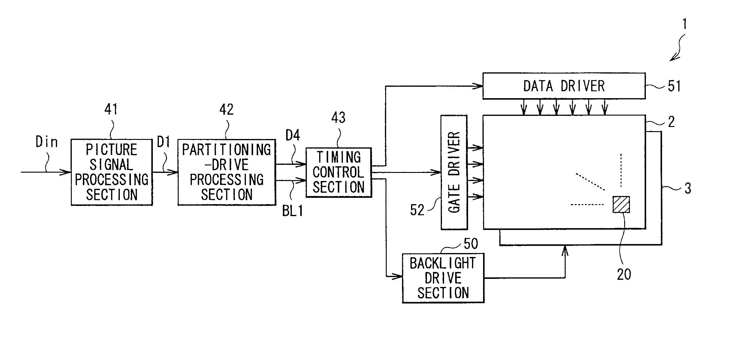
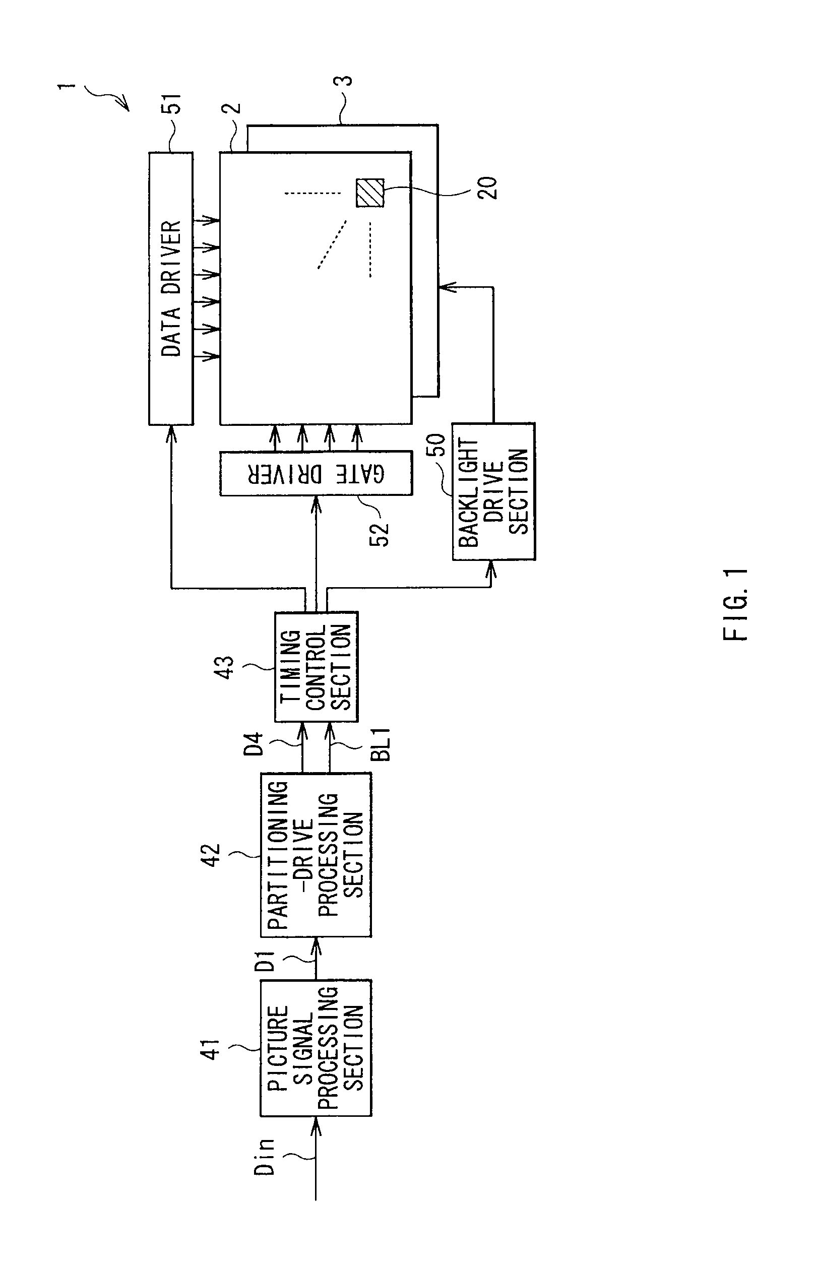
[0073]On the other hand, in the embodiment, in the partitioning-drive processing section 42, the barycenter calculation section 422A determines the barycentric position data Dg as data representing the barycentric position in a partitioned picture corresponding to each light emission sub-region 36 based on the picture signal D1. Moreover, the resolution reduction section 421 performs a predetermined resolution reduction process on the picture signal D1 to generate the picture signal D2 as the lowered-resolution picture signal. Next, the gain correction section 422B performs a predetermined gain correction on the picture signal D2 with use of the barycentric position data Dg to generate the picture signal D3 as the resultant of the gain correction. Then, in the BL level calculation section 423, the diffusion section 424 and the LCD level calculation section 425, the light-emission pattern signal BL and the partitioning-drive picture signal D4 are generated based on the...


PUM


Abstract

A liquid crystal display includes: a light source section including light-emission subsections controlled separately from one another; a liquid crystal display panel modulating, based on an input picture signal, light emitted from each light-emission subsection to display pictures; and a display control section including a partitioning-drive processing section which generates a light-emission pattern signal representing a two-dimensional pattern formed from lighting light-emission subsections and a partitioning-drive picture signal based on the input picture signal, the display control section performing a light-emission drive on each light-emission subsection based on the light-emission pattern signal and performing a display-drive on the liquid crystal display panel based on the partitioning-drive picture signal. The partitioning-drive processing section determines, based on the input picture signal, a barycentric position in a partitioned picture corresponding to each light-emission subsection, and generates the light-emission pattern signal and the partitioning-drive picture signal based on the barycentric position.

Description

BACKGROUND[0001]The present disclosure relates to a liquid crystal display including a light source section which includes a plurality of light-emission subsections.[0002]In recent years, as displays for flat-screen televisions and portable terminals, active matrix liquid crystal displays (LCDs) in which TFTs (Thin Film Transistors) are arranged for respective pixels are often used. In such liquid crystal displays, typically, pixels are individually driven by line-sequentially writing a picture signal to auxiliary capacitance elements and liquid crystal elements of the pixels from the top to the bottom of a screen.[0003]As backlights used for the liquid crystal displays, backlights using cold cathode fluorescent lamps (CCFLs) as light sources are mainstream; however, in recent years, backlights using light emitting diodes (LEDs) have appeared.[0004]As a liquid crystal display using such an LED or the like as a backlight, as described in Japanese Unexamined Patent Application Publica...

Claims


Application Information

Patent Timeline
Patent Type & Authority Applications(United States)
IPC IPC(8): G09G3/36G09G5/10
CPCG09G3/3413G09G2320/0646G09G3/3426
Inventor ASANO, MITSUYASUNISHI, TOMOHIROHIRAMATSU, TAKESHIIKAWA, NAOKI
Owner SONY CORP
Why Eureka
Try Eureka